Glow plug with combustion pressure detecting function

a technology of combustion pressure and glow plug, which is applied in the direction of instruments, lighting and heating apparatus, machines/engines, etc., can solve the problems of dispersing sensitivity of combustion pressure sensors and failing to achieve the proper detecting output, etc., and achieves high reliability, easy handling, and strong sensitivity.

Inactive Publication Date: 2006-02-16
NGK SPARK PLUG CO LTD
View PDF8 Cites 31 Cited by
  • Summary
  • Abstract
  • Description
  • Claims
  • Application Information

AI Technical Summary

Benefits of technology

[0055] In the glow plug having the combustion pressure detecting function of the invention, on the contrary, the first piezoelectric element and the second piezoelectric element are arranged in the housing root-end portion closer to the root-end than the tool engaging portion. Therefore, the sizes such as the thickness of the tool engaging portion can be selected without being influenced by the sizes and arrangements of the first piezoelectric element and the second piezoelectric element so that the tool engaging portion can be highly strong.
[0056] Moreover, the first piezoelectric element and the second piezoelectric element are arranged in the housing root-end portion so that they can be prevented, when handled, from being bit by the tool or the like. It is, therefore, possible to provide the glow plug having the combustion pressure detecting function, which can be easily handled when mounted and which has a high reliability.

Problems solved by technology

As a result, the sensitivity of the combustion pressure sensor may disperse to fail to achieve the proper detecting output.

Method used


Image

  • Glow plug with combustion pressure detecting function
  • Glow plug with combustion pressure detecting function
  • Glow plug with combustion pressure detecting function

Examples


embodiment 1

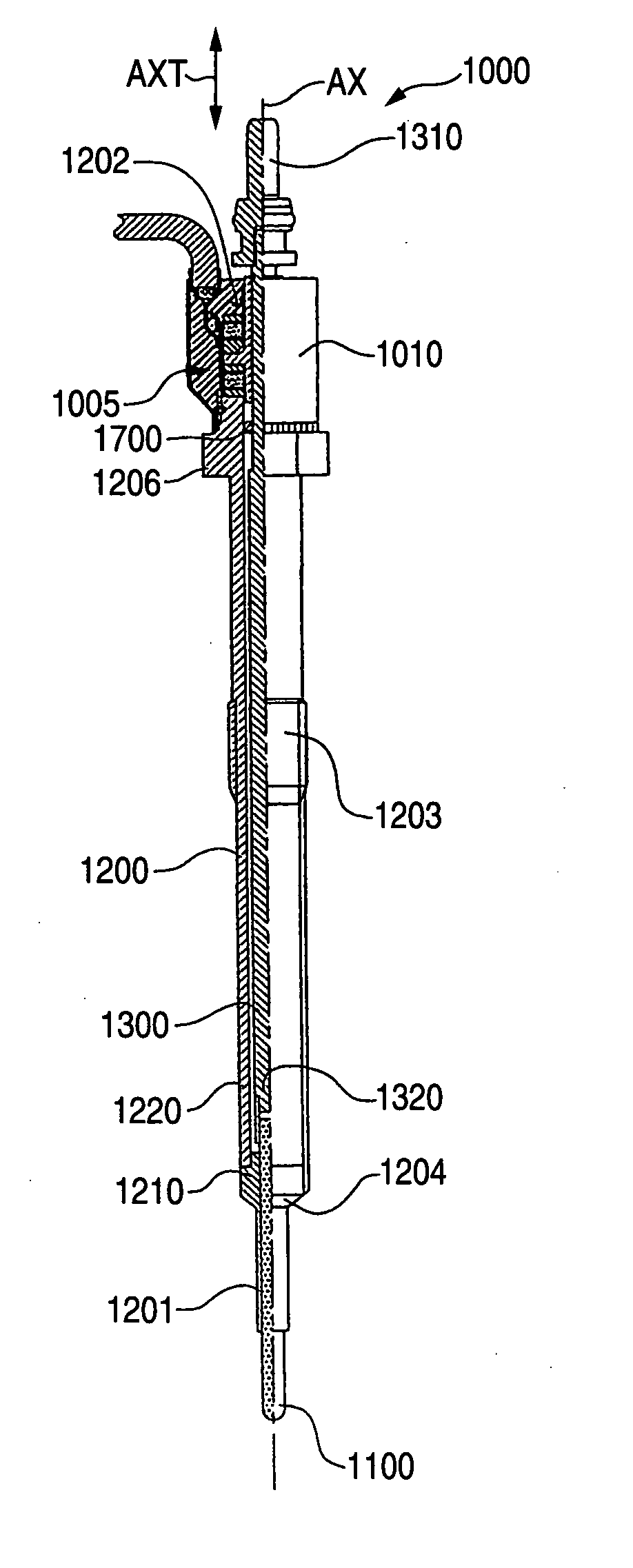
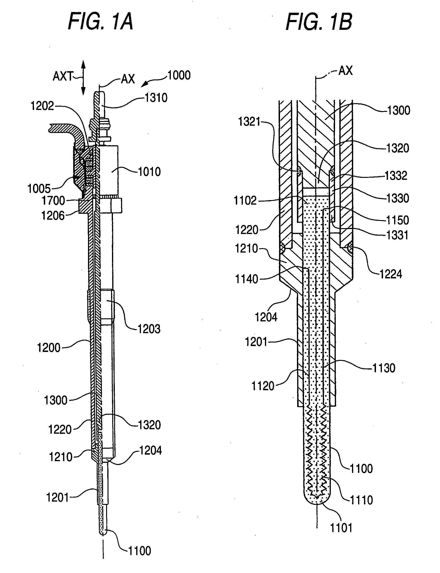
[0143] First of all, a first embodiment of the invention is described with reference to Figs. A glow plug 1000 is one capable of heating a heater member 1100 for aiding, when energized, in the start of an internal combustion engine, and having a combustion pressure sensor 1005 configured to detect the change in the combustion pressure of the internal combustion engine. This glow plug 1000 is equipped, as shown in FIG. 1A, with: a cylindrical housing 1200 extending in a direction AXT (as will be simply called the “axial direction”) along an axial line AX; a conductive center pole 1300 held in the housing 1200; and the heater member 1100 arranged on the axially leading-end side (as located on the lower side and will be simply called the “leading-end side”) of the center pole 1300.

[0144] As shown in FIG. 1B, this heater member 1100 is formed to have a substantially semispherical shape at a heater leading-end portion 1101 and to have a rod shape made of ceramics of silicon nitride. Thi...

embodiment 2

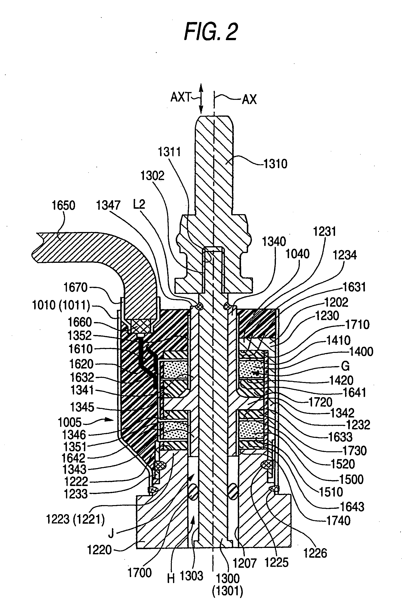
[0272] Next, a second example of the invention is described with reference to FIG. 18 to FIG. 20. In the aforementioned glow plug 1000 according to Embodiment 1, the charges produced on the two faces of the first and second piezoelectric elements 1400 and 1500 are derived to the outside through the lead wires 1610 and 1620 while being insulated from the housing 1200 or the like. Thus, the output of the combustion pressure sensor 1005 can be stably obtained irrespective of the fluctuation in the earth level of the housing 1200.

[0273] On the other hand, a glow plug 6000 according to Embodiment 2 is identical in that it uses the first and second piezoelectric elements 1400 and 1500, and in that the combustion pressure sensor is so configured that the compressive load increases in the first piezoelectric element 1400 when the center pole 1300 is displaced to the root-end side whereas the compressive load decreases in the second piezoelectric element 1500.

[0274] However, Embodiment 2 i...


PUM


Abstract

A glow plug comprising: a cylindrical housing; a heater member as defined herein; a conductive center pole as defined herein; a first piezoelectric element as defined herein; and a second piezoelectric element as defined herein, wherein each of said first piezoelectric element and said second piezoelectric element is subjected to a preload for compressing it in said axial direction and is arranged such that, when said center pole is displaced to a root-end side, a load to be applied to one of said first piezoelectric element and said second piezoelectric element for compressing the same in said axial direction increases whereas a load to be applied to the other for compressing the same in said axial direction decreases.

Description

FIELD OF THE INVENTION [0001] The present invention relates to a glow plug with a combustion pressure detecting function, which is used as a start aiding device for an internal combustion engine such as a Diesel engine and which can detect a change in the combustion pressure of the internal combustion engine. BACKGROUND THE INVENTION [0002] As a glow plug having the combustion pressure detecting function added to the glow plug for aiding the start of an internal combustion engine, there has been provided a plug having a combustion pressure sensor packaged therein, as disclosed in JP-A-2002-327919 (page 2, FIG. 1). [0003] This glow plug with the combustion pressure detecting function is equipped with: a cylindrical housing; a metallic center pole having held in the housing with one end side being exposed from the housing, and electrically conducted to a heating member; and a combustion pressure sensor for detecting the combustion pressure in terms of the force which is caused to act ...

Claims


Application Information

Patent Timeline
Patent Type & Authority Applications(United States)
IPC IPC(8): F23Q7/00F02M65/00G01M15/00
CPCF02P19/028F23Q2007/002G01L23/22F23Q7/001
Inventor YAMADA, TATSUNORIYAMADA, YUICHIOKAZAKI, KOJIMATSUI, MASAYOSHIOZEKI, KEIJISUZUKI, TAKAHIRO
Owner NGK SPARK PLUG CO LTD
Why Eureka
Try Eureka