Quick strike pneumatic pressure regulator

a pneumatic pressure regulator and quick strike technology, which is applied in the direction of portable drilling machines, combustion types, lighting and heating apparatus, etc., can solve the problems of not being able to carry with the user, the tank is too large or heavy to be carried with the user, and the regulator is not portabl

Inactive Publication Date: 2006-02-16
PETTY ERIC M
View PDF17 Cites 21 Cited by
  • Summary
  • Abstract
  • Description
  • Claims
  • Application Information

AI Technical Summary

Benefits of technology

[0009] It is an objective of the present invention to provide a portable pressure regulator for use with pneumatic operated equipment. The pressure regulator is designed for mounting on the belt of a user. The regulator includes a coupling mechanism for attaching a tank of compressed air. This configuration of pressure regulator provides a number of advantages to systems that are currently available.
[0012] The regulator may include an adjustment for the pressure. The pressure adjustment device allows the user to set or adjust the pressure in the hose. The pressure may require adjustment based upon the tool or equipment that is connected to the other end of the hose. The regulator may additionally include a pressure gauge oriented on the regulator housing to allow viewing the pressure in the hose. The pressure gauge allows the operator to visually see and set the pressure in the hose. If the user is torqueing nuts on a car they may require a higher pressure than a person air brushing the paint on a car. An additional component of the regulator may include a burp valve that allows the user to burp or bleed pressure from the hose prior to disconnecting a tool.
[0014] Another advantage of this invention is the pressure in the hose connected to the pneumatic tool is lower. The lower pressure in the hose is safer should a leak or break take place in the hose. This is a safer design as opposed to attaching the regulator to the pneumatic equipment and filling the hose with high-pressure gas.
[0015] Still another advantage if this invention is the orientation of the vent hole that vents pressure away from the user to reduce the possibility that the quick release of air will not come in contact with users face while they are removing the bottle from the regulator.

Problems solved by technology

One of the major problems with pressure regulators of this type is that the regulator is not portable, or the tank is too large or heavy to be carried with the user.
While these patents allow for a pressure regulator that is attached to the compressed air tank, the patents are not intended for use with pneumatic tools, nor are they intended for use outside of water.
The regulator is also not intended for mounting on the belt of the user.
While this patent allows for a pressure regulator that is attached to the compressed air tank and controls a pneumatic power tool, the regulator is not intended to be mounted on a belt.
While this patent is intended for use with a pneumatic tool, the regulator is not intended to be mounted on the user's belt.
The weight of these components increases the fatigue factor as the operator uses the nailing machine.

Method used


Image

  • Quick strike pneumatic pressure regulator
  • Quick strike pneumatic pressure regulator
  • Quick strike pneumatic pressure regulator

Examples


Embodiment Construction

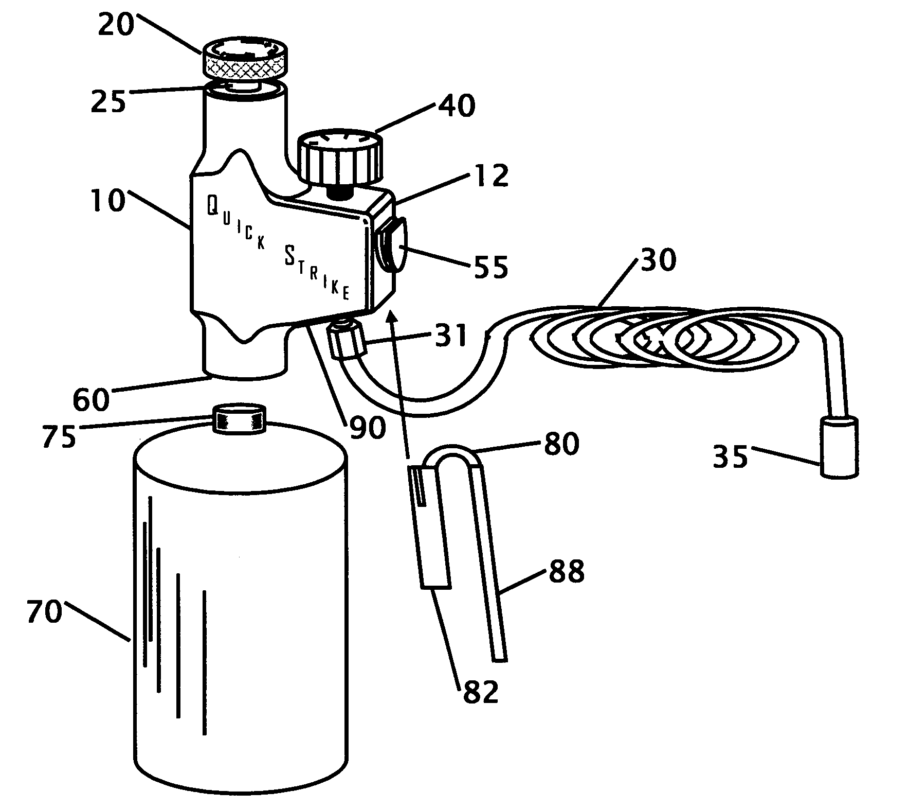
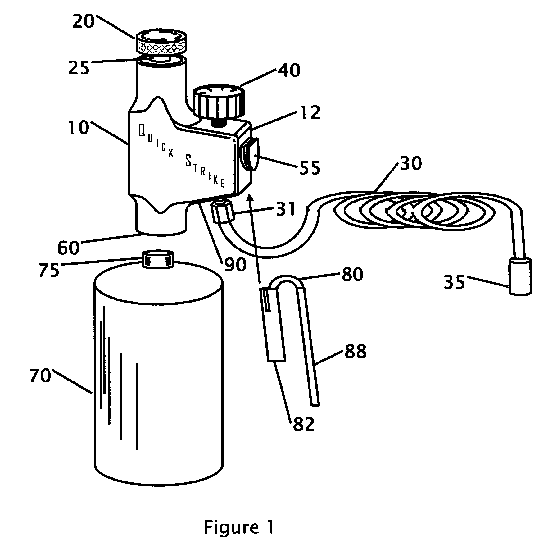
[0020] Referring to FIG. 1, that shows a perspective view of the regulator connected to a tank 70, air hose 30 and the regulator 10. In the preferred embodiment the regulator is made from a one piece aluminum body. On one end of the regulator a pressure adjustment knob, item 20, is located. The pressure adjustment knob allows the operator to change or set the pressure on the output side of the pressure regulator. The pressure adjustment knob is knurled around the side of the knob to allow the operator to more easily grip the knob. The under side of the knob threads into the pressure regulator, item 25. As the knob is turned and threads into the regulator body the pressure can be increased or decreased. The pressure being set can be viewed on the pressure gauge, item 40 located on the top of the regulator such that it can be viewed while making adjustment to the pressure using knob 20. The position of the pressure gauge allows the operator to make adjustments without having to tip th...


PUM

PropertyMeasurementUnit
Pressureaaaaaaaaaa

Abstract

A pressure regulator is disclosed that relates to a belt mounted portable pneumatic pressure regulator where a CO2, compressed tank, or similar pressurized canister can be connected to the pressure regulator and a discharge hose can be connected to the regulator. The discharge hose provides a regulated supply of pneumatic air for an air driven power tool, paint gun, or other piece of equipment that operates from a supply of pressurized air. The regulator may include a pressure gauge, adjusting knob, and a pressure relief or burst valve.

Description

CROSS REFERENCE TO RELATED APPLICATION [0001] This application is a continuation-in-part of U.S. patent application Ser. No. 11 / 866,598, filed Jun. 14, 2004FIELD OF THE INVENTION [0002] The present invention relates generally to a portable pneumatic pressure regulator. More specifically, it relates to a belt or waist mounted pneumatic pressure regulator where a CO2 or compressed air supply can be connected to the pressure regulator and a hose can be connected to the pressure regulated discharge side of the regulator. The hose provides a regulated supply of pressurized gas or air to an air driven power tool, paint gun, or other piece of equipment that operates from a supply of pressurized gas or air. BACKGROUND OF THE INVENTION [0003] Many pressure regulator inventions are used to reduce the pressure from a tank of compressed gas or liquid gas. Most of these inventions are used where the pressurized tank is not transportable, or the tank is installed onto or within the equipment that...

Claims


Application Information

Patent Timeline
IPC IPC(8): B27C3/08A62C13/66A62C15/00B05B1/30B05B7/32B05B9/03B05B9/08F23D11/24F23D14/28F41B11/32
CPCF41B11/724B05B9/03B05B9/08B05B7/02B05B1/30
Inventor PETTY, ERIC M.
Owner PETTY ERIC M
Why Eureka
Try Eureka