Transaxle of multi-wheel drive vehicle

a multi-wheel drive, auxiliary drive technology, applied in mechanical actuated clutches, transportation and packaging, mechanical equipment, etc., can solve the problems of heavy steering operation, waste of energy consumption, and operator's troublesome manipulation

Inactive Publication Date: 2006-02-16
KANZAKI KOKYUKOKI MFG
View PDF6 Cites 24 Cited by
  • Summary
  • Abstract
  • Description
  • Claims
  • Application Information

AI Technical Summary

Benefits of technology

[0010] An object of the present invention is to provide a transaxle supporting left and right axles drivingly connected respective left and right auxiliary drive wheels to be adapted to a vehicle having a main drive wheel and the left and right auxiliary drive wheels so that the vehicle usually travels by driving only the main drive wheel, and the auxiliary drive wheels are driven when the main drive wheel slips, wherein, even if high load is applied on the auxiliary drive wheel, the axles which have received rotary force driving the main drive wheel so as to drive the respective auxiliary drive wheels can smoothly return to be free from the rotary force driving the main drive wheel when the main drive wheel escapes from slipping.

Problems solved by technology

The problem of the vehicle is to require an operator's troublesome manipulation.
If the manipulation is mistaken or wrong, the vehicle may unexpectedly travel by the six-wheel drive, thereby causing waste energy consumption, or causing heavy steering operation.
However, if load on the auxiliary drive wheel is large during the slip of the main drive wheel, the rollers may be firmly engaged between the inner and outer rings so that they cannot separate the inner and outer rings from each other after the main drive wheel escapes from slipping.
If the problem happens, the vehicle has to travel with unexpected drive of the auxiliary drive wheels, thereby reducing driving efficiency and steering capacity.

Method used


Image

  • Transaxle of multi-wheel drive vehicle
  • Transaxle of multi-wheel drive vehicle
  • Transaxle of multi-wheel drive vehicle

Examples


first embodiment

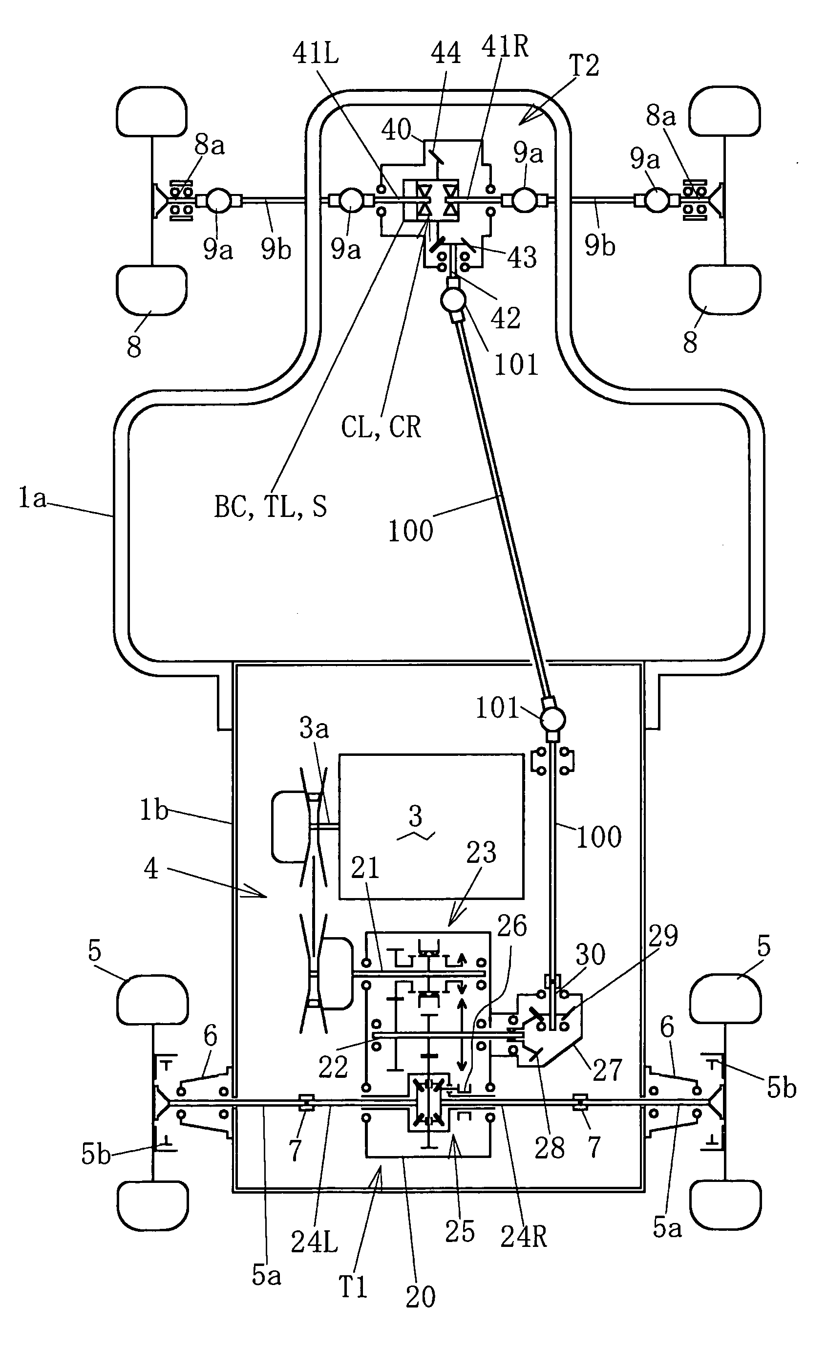
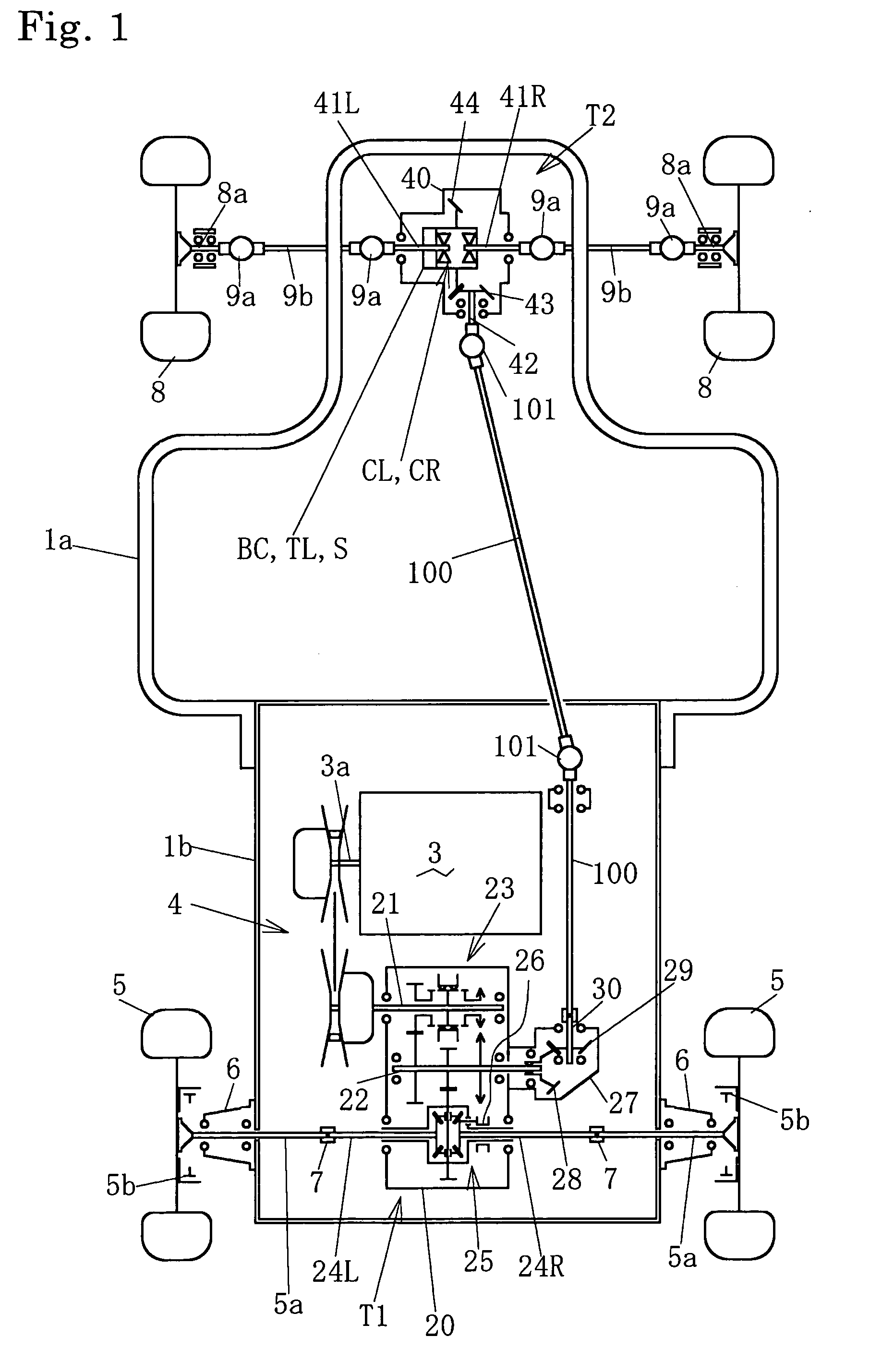
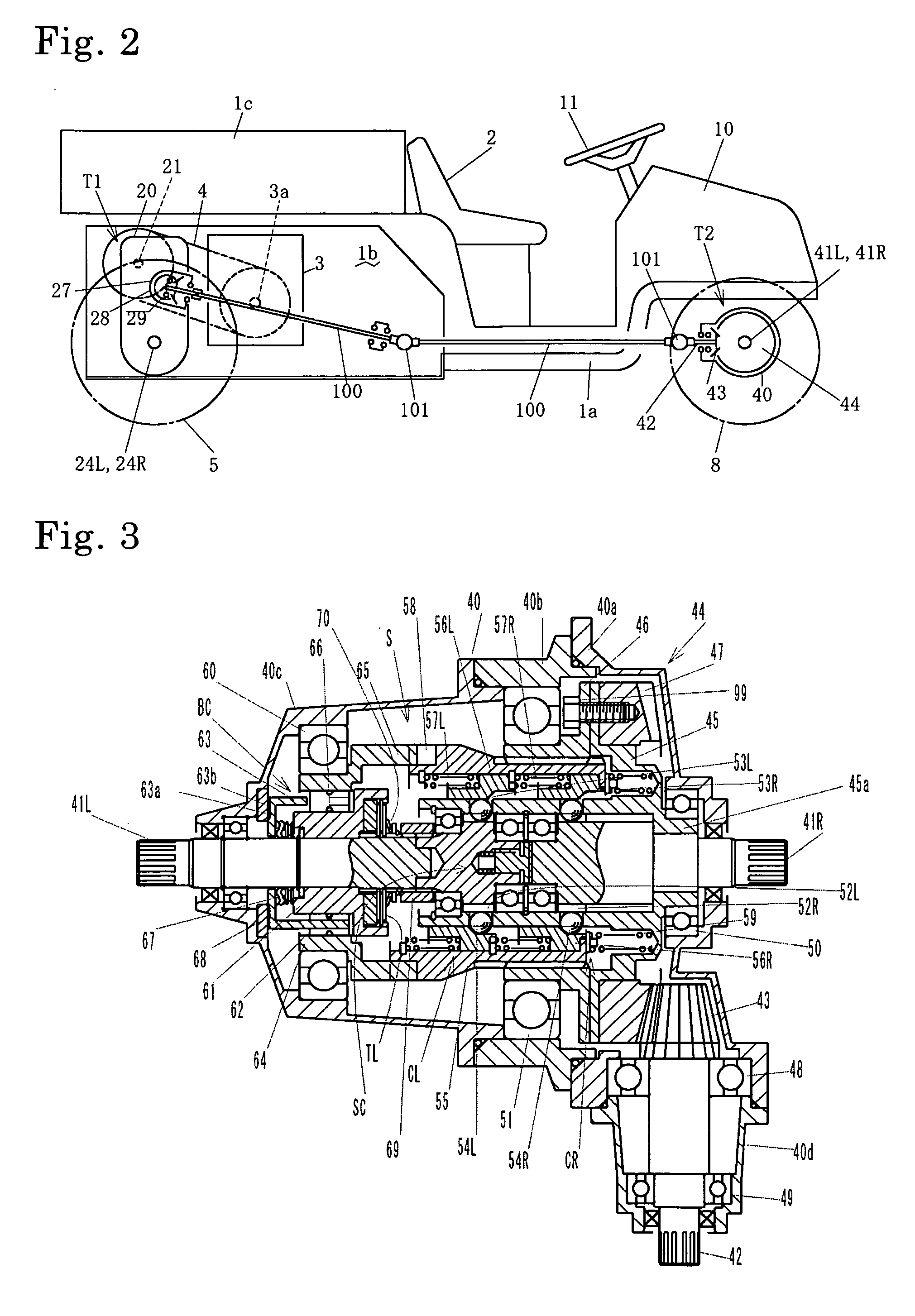
[0057] An interior structure of auxiliary transaxle T2 will be described with reference to FIG. 3. Auxiliary transaxle T2 includes a housing 40 supporting left and right axles 41L and 41R and an input shaft 42. Axles 41L and 41R are extended laterally outward from respective left and right side ends of housing 40. Input shaft 42 is disposed in perpendicular to axles 41L and 41R, and projects outward (rearward) from housing 40 to be drivingly connected to output shaft 30 via a propeller shaft 100 and universal joints 101 so as to receive the rotary force from main transaxle T1 synchronized to the rotation of main drive wheels 5.

[0058] In housing 40, a bevel pinion 43 is formed on an (front) end of input shaft 42, and meshes with a bevel center gear 44 coaxially and relatively rotatably fitted around axles 41L and 41R.

[0059] A gear ratio of center gear 44 to bevel pinion 43 is set so that, while clutches CL and CR are engaged, total peripheral speeds of main drive wheels 5 become 11...

fourth embodiment

[0099] Auxiliary transaxle T2 of this embodiment is advantageous in that, even when one of left and right auxiliary drive wheels 8 floats on the ground, the other auxiliary drive wheel 8 gripping the ground is effectively slowed down by slipping of main drive wheel 5 so as to engage corresponding two-way clutch BCL or BCR. Therefore, auxiliary transaxle T2 of the fourth embodiment requires no slip clutch SC for mutually connecting axles 41L and 41R by a small frictional force, thereby ensuring smooth rotation of auxiliary drive wheels 8 without frictional resistance therebetween during turning of the vehicle.

[0100] Referring to a fifth embodiment of auxiliary transaxle T2 shown in FIG. 9, description will be given of only points distinguished from the third embodiment shown in FIGS. 6 and 7. Description of members or portions, which are identical or similar to those in the third embodiment and are designated by the same reference numerals, is omitted unless any of them is to be spec...

third embodiment

[0104] Proximal portions of axles 41L and 41R are coaxially disposed in cylinder shaft 45a so as to face each other. Proximal portions of axles 41L and 41R in cylinder shaft 45a are diametrically expanded so as to serve as respective transmission members 80L and 80R. Each of clutches CL and CR is interposed between cylindrical shaft 45a and each of transmission members 80L and 80R. Description of mechanism of clutches CL and CR is omitted because it is similar to that of clutches CL and CR according to the

[0105] One end of cylindrical shaft 45a, formed with cam 45b, is extended distally from bearing 50a into the second chamber so as to engage with cam 85a fixed to one end surface of switch operation member 85. In the second chamber, two-way clutch BC is constructed so that inner ring 61 is fitted on axle 41L, and switch operation member 85 is spline-fitted on the outer peripheral surface of outer ring 64 so as to be not relatively rotatable but axially slidable on outer ring 64. Dis...


PUM


Abstract

A transaxle for auxiliary wheels of a vehicle having a main drive wheel and left and right auxiliary drive wheels, comprises: a gear to which a rotary force for driving the main drive wheel is distributed; a pair of left and right axles drivingly connected to the respective left and right auxiliary drive wheels; a pair of clutches, wherein one of the clutches is interposed between the gear and the left axle, and the other clutch is interposed between the gear and the right axle; judging means for judging whether or not the main drive wheel slips; and a shift mechanism for engaging and disengaging the pair of clutches based on the judgment of the judging means. The judging means comprises a two-way clutch interposed between the gear and the pair of axles, which is engaged when rotary speed of the gear exceeds rotary speed of at least one of the axles. Alternatively, the judging means comprises: a sensor for detecting rotary speed of the gear; a sensor for detecting rotary speed of at least one of the axles; and a controller for controlling the shift mechanism. The controller receives signals from both of the sensors so as to judge whether or not the main drive wheel slips.

Description

BACKGROUND OF THE INVENTION [0001] 1. Field of the Invention [0002] The present invention relates to a transaxle for auxiliary drive wheels of a multi-wheel drive vehicle having main drive wheels and auxiliary drive wheels, wherein an auxiliary transaxle for driving the auxiliary drive wheels is automatically selectively put into either a drive-on mode for driving the auxiliary drive wheels by power transmitted from a main transaxle for main drive wheels or a drive-off mode for isolating the auxiliary drive wheels from the power transmitted from the transaxle for main drive wheels. [0003] 2. Related Art [0004] Conventionally, as disclosed in Japanese Laid Open Gazette No. 2002-59754, there is a well-known six-wheel drive utility vehicle as an example of multi-wheel drive vehicles. The six drive wheels of the vehicle are left and right rear main drive wheels, left and right middle main drive wheels, and left and right front auxiliary drive wheels. The vehicle is equipped with a first...

Claims


Application Information

Patent Timeline
Patent Type & Authority Applications(United States)
IPC IPC(8): B60K17/35
CPCB60K17/344B60K17/35B60W2520/26B60K23/08B60K17/3505
Inventor IMA, AKIHIROHASEGAWA, TOSHIYUKI
Owner KANZAKI KOKYUKOKI MFG
Why Eureka
Try Eureka