Forged hammermill hammer
a forged hammer and hammer head technology, applied in the field of forged hammer mill hammers, can solve the problems of lengthening the overall life of the hammer, and achieve the effects of improving the secure end of free swinging hammers, reducing susceptibility to rod hole elongation, and improving the strength of the rod hol
- Summary
- Abstract
- Description
- Claims
- Application Information
AI Technical Summary
Benefits of technology
Problems solved by technology
Method used
Image
Examples
first embodiment
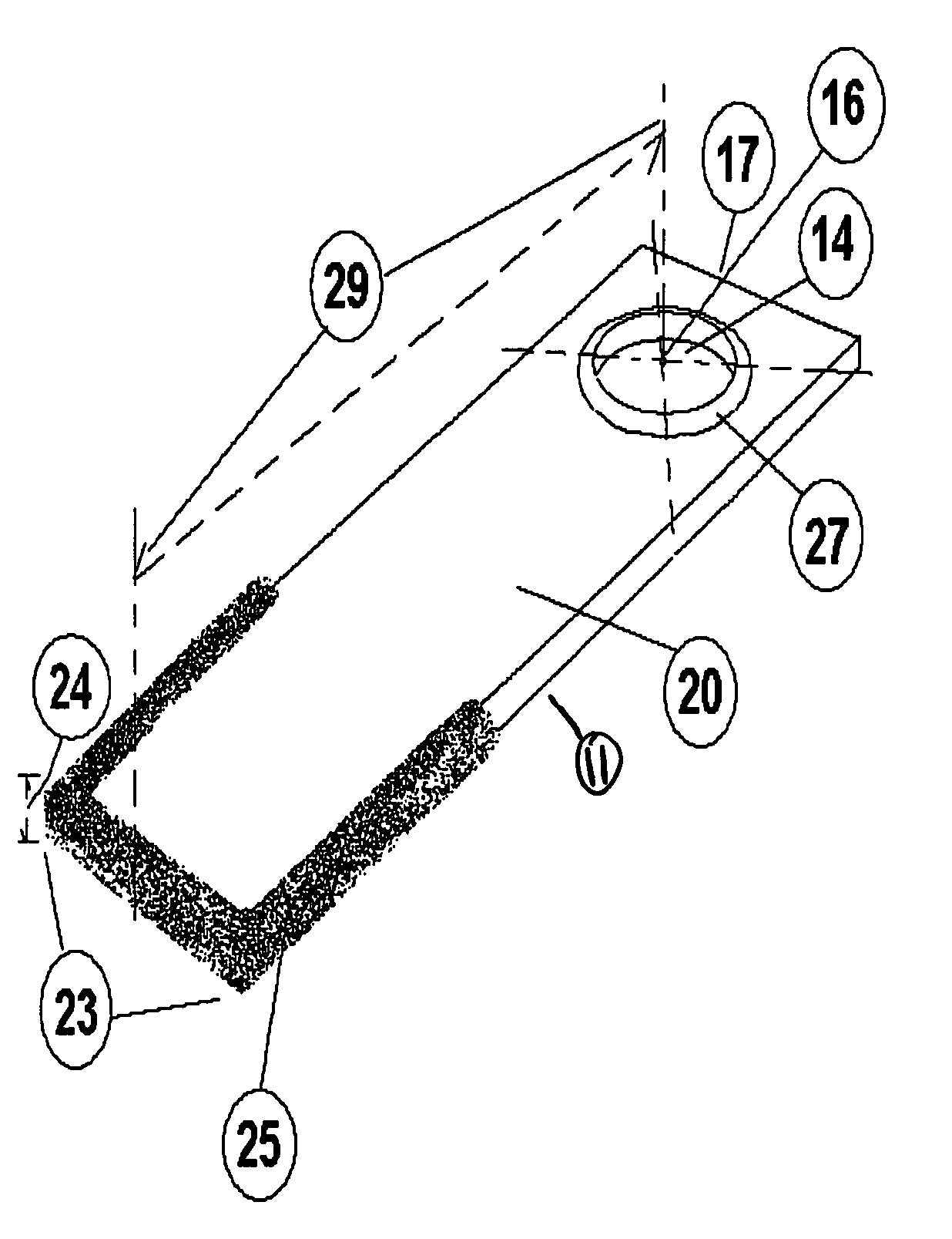
[0055]FIGS. 5-7 show the present invention, particularly hammers to be installed in the hammermill assembly. FIG. 5 presents a perspective view of this embodiment of the improved hammer 11. As shown, the first end of the hammer 17 is for securement of the invention within the hammermill assembly 1 (not shown) by insertion of the hammer rod 9 through hammer rod hole 14 of the hammer 11. In FIG. 5 the center of the rod hole 16 is highlighted. The distance from the center of rod hole 16 to the contact or second end of the hammer 23 is defined as the hammer swing length 29. Typically, the hammer swing length 29 of the present embodiment is in the range of eight (8) to ten (10) inches with most applications measuring eight and five thirty seconds inches (8 5 / 32″) to nine and five thirty seconds (9 5 / 32″).
[0056] In the embodiment of the hammer 11 shown in FIGS. 5-7, the hammer rod hole 14 is surrounded by a single stage hammer rod hole shoulder 27. In this embodiment, the hammer shoulder ...
second embodiment
[0060]FIG. 8 best illustrates the curved, rounded nature of the present invention, as shown by the arcuate edges from the first end of the hammer 17 and continuing through hammer neck 20 to the second hammer end 23. To further reduce hammer weight, hammer neck holes 22 have been placed in the hammer neck 20. The hammer neck holes 22 may be asymmetrical as shown or symmetrical to balance the hammer 11. The arcuate, circular or bowed nature of the hammer neck holes 22 as shown allows transmission and dissipation of the stresses produced at the first end of the hammer 17 through and along the neck of the hammer 20.
[0061] As emphasized and illustrated by FIGS. 8 and 10, the reduction in hammer neck thickness and weight allowed through both the combination of the hammer neck shape and hammer neck holes 22 provide improved hammer neck strength at reduced weight therein allowing increased thickness at the first and second ends of the hammer, 17 and 23, respectively, to improve both the sec...
third embodiment
[0063]FIG. 11 illustrates the curved hammer neck edges 30 which give the hammer 11 an hourglass shape starting below the hammer rod hole 14 and at the first end of the hammer 17 and continuing through the hammer neck 20 to the second end of the hammer 23. Incorporation of this shape into the present invention assists with hammer weight reduction while also reducing the vibration of the hammer 11 as it rotates in the hammer mill and absorbs the shock of contact with comminution materials.
[0064] As shown and illustrated by FIG. 13 which provides a side view of the present embodiment, the first end of the hammer 17, the neck 20 and the second end of the hammer 23 are of a substantially similar thickness with the exception of the stage 1 and 2 hammer rod hole reinforcement shoulders, 27 and 28, to maintain the hammer's reduced weight over the present art. As emphasized and further illustrated by FIGS. 11-13, the reduction in the hammer profile and weight allowed through both the combina...
PUM
 Abstract
Description
Claims
Application Information
 - R&D
- Intellectual Property
- Life Sciences
- Materials
- Tech Scout
- Unparalleled Data Quality
- Higher Quality Content
- 60% Fewer Hallucinations
Browse by: Latest US Patents, China's latest patents, Technical Efficacy Thesaurus, Application Domain, Technology Topic, Popular Technical Reports.
© 2025 PatSnap. All rights reserved.Legal|Privacy policy|Modern Slavery Act Transparency Statement|Sitemap|About US| Contact US: help@patsnap.com


