Circularly polarized broadcast panel system and method using a parasitic dipole

a dipole and circular polarization technology, applied in the direction of slot antennas, antenna feed intermediates, antennas, etc., can solve the problem that the antennas of the bow-tie panel are not known for propagating electromagnetic radiation

Inactive Publication Date: 2006-02-16
SPX CORP
View PDF11 Cites 21 Cited by
  • Summary
  • Abstract
  • Description
  • Claims
  • Application Information

AI Technical Summary

Benefits of technology

[0005] In accordance with another embodiment of the present invention, a panel antenna is provided, comprising, a first substantially flat broadband radiating means for radiating predominant first electromagnetic field orientation, and a second radiating means for radiating predominant second electromagnetic field orientation, an imaging means for providing a ground plane effect, wherein the second radiating means is disposed substantially parallel to and displaced from a plane of the first radiating means, and oriented at an angle that is skewed from an axis of symmetry of the first radiating means and a midpoint of the first radiating means substantially crosses the axis of symmetry, and the imaging means is disposed substantially parallel to the first radiating means and on an opposite face of the first radiating means from the second radiating means.

Problems solved by technology

However, bow-tie panel antennas are not known for propagating electromagnetic radiation having a circular polarization.

Method used


Image

  • Circularly polarized broadcast panel system and method using a parasitic dipole
  • Circularly polarized broadcast panel system and method using a parasitic dipole
  • Circularly polarized broadcast panel system and method using a parasitic dipole

Examples


Embodiment Construction

[0015] The invention will now be described with reference to the drawing figures, in which like reference numerals refer to like parts throughout.

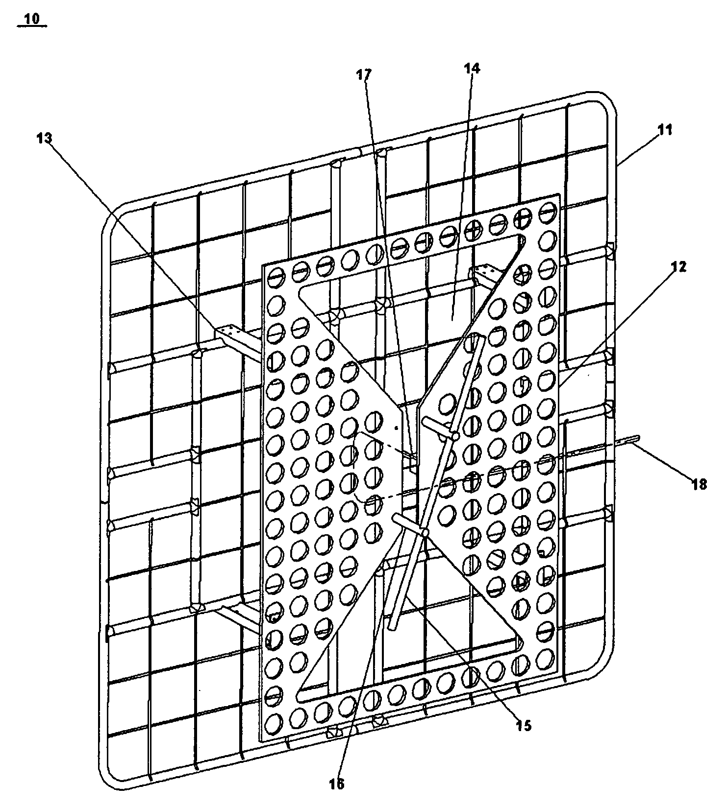
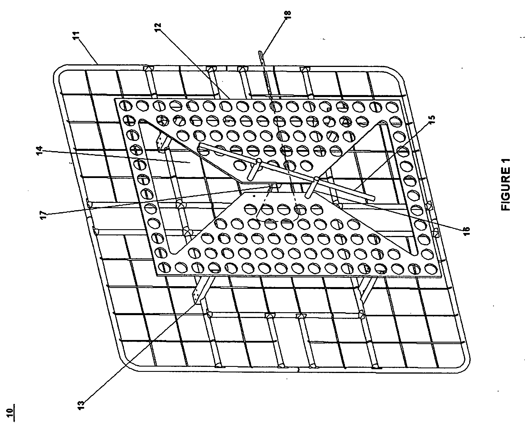
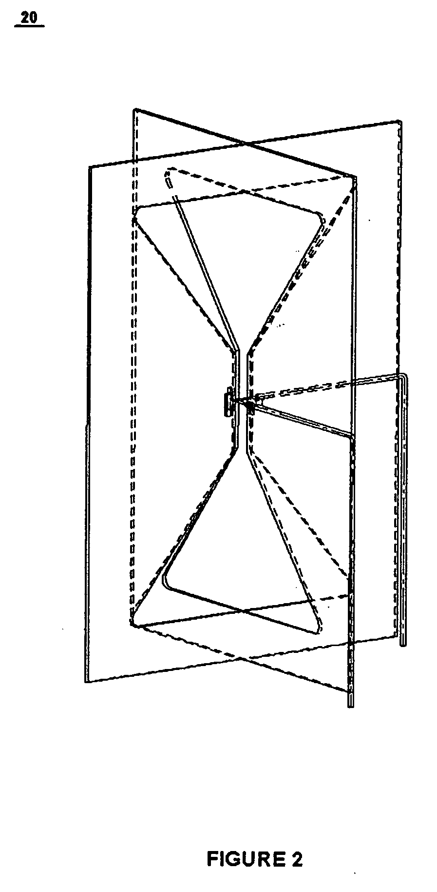
[0016] Various attempts have been made in the antenna community to modifiy the simple structure provided by a panel antenna to have multiple degrees of freedom. The closest approach known using panel antennas is discussed in U.S. Pat. No. 6,762,730, titled “Crossed Bow-tie Slot Antenna,” by the present inventor, John Schadler, the disclosure of which is hereby incorporated by reference in its entirety. This approach superimposes bow-tie slot panels in separate planes of azimuth to form complementary electromagnetic field vectors from the independent slot panels. However, as detailed in the No. 6,762,730 patent, the resultant pattern provides omni-directional horizontal field components, rather than circular polarization.

[0017] Alternatively, ring-style or crossed dipole antennas are known to provide circular polarization. However, these ...


PUM


Abstract

A bow-tie slot panel antenna is described, having a parasitic element positioned at an orientation from the slot to generate orthogonal fields. By adjusting the coupling ratios, dimensions and angle of orientation of the parasitic element, circularly polarized fields can be effectively produced, using the panel antenna as the primary radiator.

Description

FIELD OF THE INVENTION [0001] The present invention relates generally to circularly polarized broadcast antennas. More particularly, the present invention relates to a circularly polarized broadcast antenna using an askew radiating element parasitically fed by a slotted panel. BACKGROUND OF THE INVENTION [0002] Slotted antenna systems are well known in the art as providing radiation patterns similar to dipole antennas. Antennas using a slot or a series of slots in a flat, electrically large surface are typically referred to as panel antennas. Panel antennas having a bow-tie-shaped slot are known to be multi-band (based on the width and shape of the bow-tie). However, bow-tie panel antennas are not known for propagating electromagnetic radiation having a circular polarization. [0003] Therefore, there has been a longstanding need in the antenna community for a panel antenna to provide circularly-polarized electromagnetic radiation. SUMMARY OF THE INVENTION [0004] The foregoing needs a...

Claims


Application Information

Patent Timeline
Patent Type & Authority Applications(United States)
IPC IPC(8): H01Q13/10
CPCH01Q13/10H01Q9/28
Inventor SCHADLER, JOHN L.
Owner SPX CORP
Why Eureka
Try Eureka