Composite display unit and electric apparatus using this

a technology of display unit and electric apparatus, applied in the field of composite display unit, can solve the problems of large electrical power consumption, severe attenuation of light, intense cell consumption, etc., and achieve the effect of conserving spa

Inactive Publication Date: 2006-02-16
ROHM CO LTD
View PDF6 Cites 23 Cited by
  • Summary
  • Abstract
  • Description
  • Claims
  • Application Information

AI Technical Summary

Benefits of technology

[0011] Therefore, an object of the present invention is to provide a composite display unit that makes it possible to conserve space and clearly display each of a plurality of display elements while individually or simultaneously displaying displays of a plurality of types.

Problems solved by technology

However, dot-matrix displays that employ a back light consume a large amount of electrical power and cell consumption is intense.
On the other hand, when a display element with a different display system is provided in another location, this is an impediment to miniaturization of the electrical device and, when the two display elements are stacked, the attenuation of light is severe.
There is then the problem that the visibility of the display is reduced.
Furthermore, although applications are not limited to the display of an electrical device and there is a demand to use a plurality of display elements side by side such as a display element that uses an LED or the like, and a liquid crystal display element, there is the problem that the arrangement of the display elements side by side takes up space and one of the display elements cannot be seen when same are stacked.
As mentioned earlier, when a plurality of types of display elements are arranged side by side in cases where there is no need for a simultaneous display but a plurality of types of displays are to be implemented, there is the problem that such an arrangement takes up space and, when the display elements are stacked, there is the problem that the display of the lower display element is hard to see.
As a result, in the case of the liquid crystal display unit that is disclosed inth is publication, there is the problem that the display of the lower liquid crystal panel in particular is hard to see and that both display images cannot be seen clearly.
In addition, because light passes through the polarization plate a total of four times in the reflective-type liquid crystal display element before being emitted, the usage efficiency of light is even poorer.
As a result, it is extremely difficult to improve the visibility of the reflective-type liquid crystal display element and the other display element by overlapping these display elements.

Method used


Image

  • Composite display unit and electric apparatus using this
  • Composite display unit and electric apparatus using this
  • Composite display unit and electric apparatus using this

Examples


first embodiment

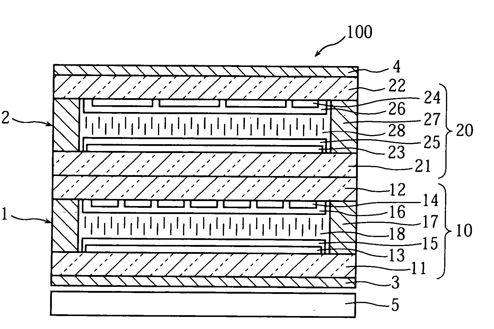
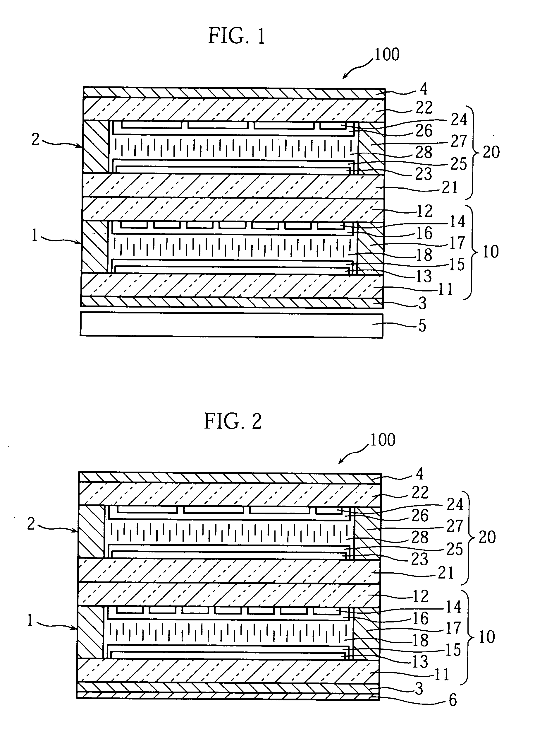
[0025]FIG. 1 shows the composite display unit of the present invention. As shown in FIG. 1, the composite display unit 100 is provided by over lapping the first display element 1 and second display element 2. The first display element 1 is constituted comprising a liquid crystal panel 10 in which a liquid crystal layer 18 is held between first and second transparent substrates 11 and 12 respectively, a reflective polarization plate 3 that is provided on the side of the first transparent substrate 11 and a polarization plate 4 that is provided on the side of the second display element 2. In the example shown in FIG. 1, the reflective polarization plate 3 and polarization plate 4 are common to the first display element 1 and the second display element 2. This reflective polarization plate 3 is characterized in that same transmits light that oscillates in a specified direction and reflects light that oscillates in a direction intersecting with the specified direction and is joined dire...

third embodiment

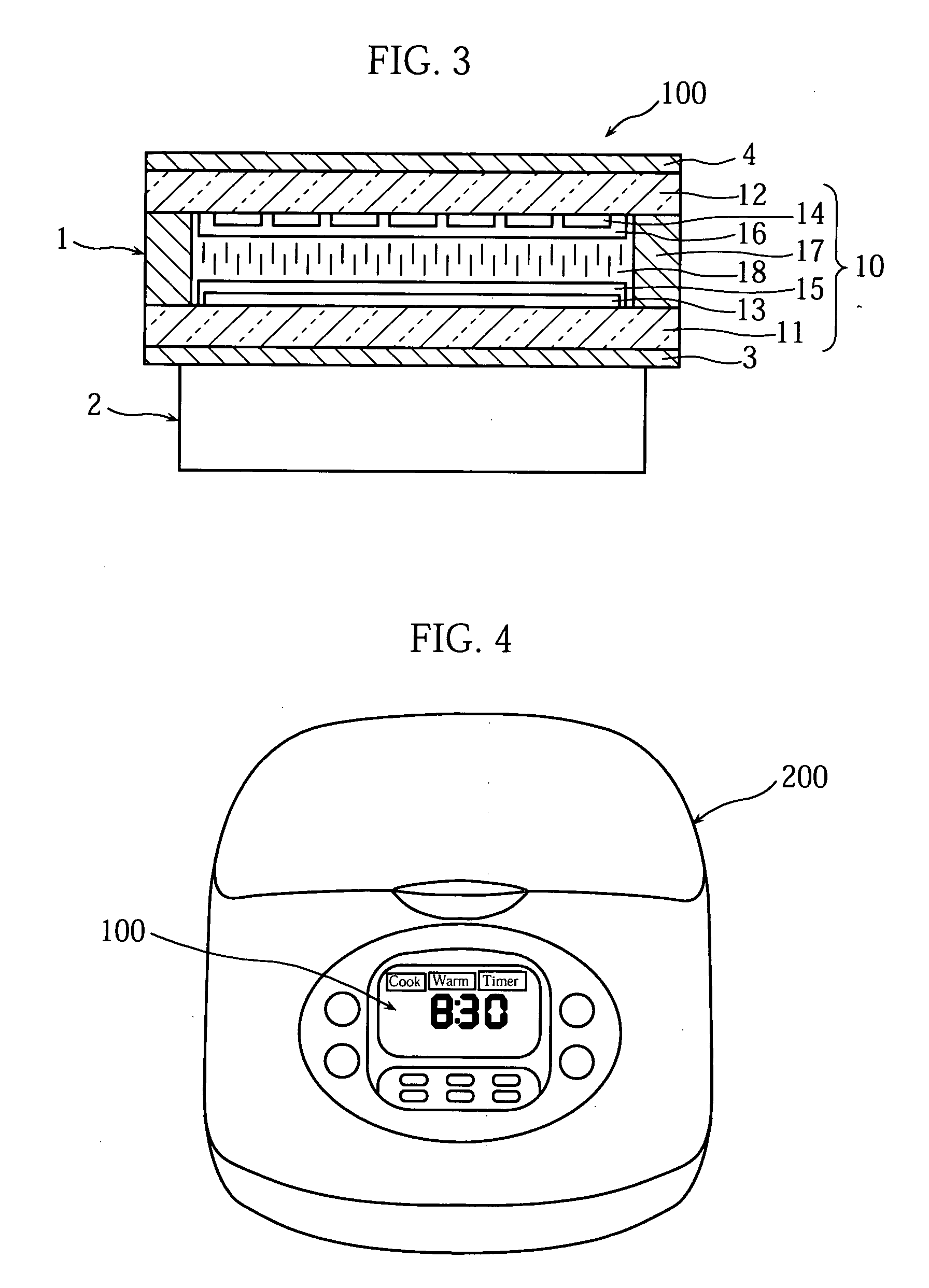
[0048]FIG. 3 shows the composite display unit 100 of the present invention. In this embodiment, the first display element 1, which is rendered by providing the reflective polarization plate 3 and polarization plate 4 on both sides of the liquid crystal panel 10 with the same constitution as that mentioned earlier is constituted to overlap the second display element 2. In addition to it being possible for the second display element 2 to employ a liquid crystal display element that is produced by providing a polarization plate on both sides of the liquid crystal panel 20 in which a liquid crystal layer is held between two transparent substrates that is the same as the second display element 2, for example, it is also possible to combine a display element that is constituted by lining up light-emitting diodes (LED) in the form of a matrix or a display element that is constituted by arranging cold cathode tubes, with the existing display element.

[0049] So to in this constitution, if TN ...


PUM

PropertyMeasurementUnit
refractive indexaaaaaaaaaa
twist angleaaaaaaaaaa
transparentaaaaaaaaaa

Abstract

A first display element 1 and a second display element 2 are provided in a stacked configuration. The first display element 1 includes a liquid crystal panel 10 in which a liquid crystal layer 18 is held between first and second transparent substrates 11 and 12, a reflective polarization plate 3 that is provided on the side of the first transparent substrate 11 and a polarization plate 4 that is provided on the side of the second display element 2. In the example shown in FIG. 1, the reflective polarization plate 3 and polarization plate 4 are common to the first display element 1 and the second display element 2. The reflective polarization plate 3 transmits light that oscillates in a specified direction and reflects light that oscillates in a direction intersecting with the specified direction, and is joined directly to the liquid crystal panel 10 via an adhesive layer with a uniform refractive index.

Description

TECHNICAL FIELD [0001] The present invention relates to a composite display unit produced by stacking two or more display elements and an electrical device employing the composite display unit. More precisely, the present invention relates to a composite display unit that renders low power consumption and space savings possible and allows respective display elements to produce a bright display with a high contrast by implementing constitution by combining a liquid crystal display element, which employs a reflective polarization plate that allows light oscillating in a specified direction to pass and reflects light that oscillates in a direction intersecting with the specified direction with another display element, as well as to an electrical device employing the composite display unit. BACKGROUND ART [0002] Conventionally, in the case of an electrical device such as a rice cooker, for example, liquid crystal display elements are generally used to display the operating guide and so ...

Claims


Application Information

Patent Timeline
Patent Type & Authority Applications(United States)
IPC IPC(8): G02F1/1335G02F1/1347G02B5/30G02F1/13G02F1/13357
CPCG02F1/13471G02F1/133536G02F1/1335
Inventor TANAKA, MASASHITORIUMI, YUKITOSHIMADA, KENICHI
Owner ROHM CO LTD
Why Eureka
Try Eureka