
Therapy prediction and optimization for renal failure blood therapy, especially home hemodialysis

a technology for predicting and optimizing hemodialysis and hemodialysis, which is applied in the field of dialysis systems, can solve the problems of insufficient convective clearance, limited acceptance of the date, and the simple drag of the ultrafiltrate removal, so as to improve the quality of life, improve the effect of hemodialysis, and accurately predict the steady sta

Active Publication Date: 2017-06-29
BAXTER INT INC +1
View PDF1 Cites 1 Cited by
  • Summary
  • Abstract
  • Description
  • Claims
  • Application Information

AI Technical Summary

Benefits of technology

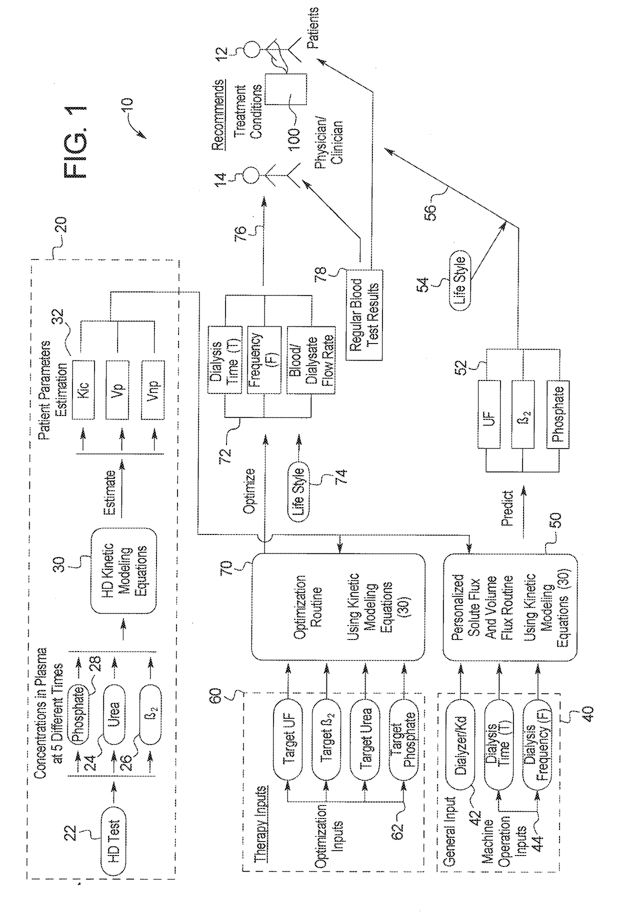
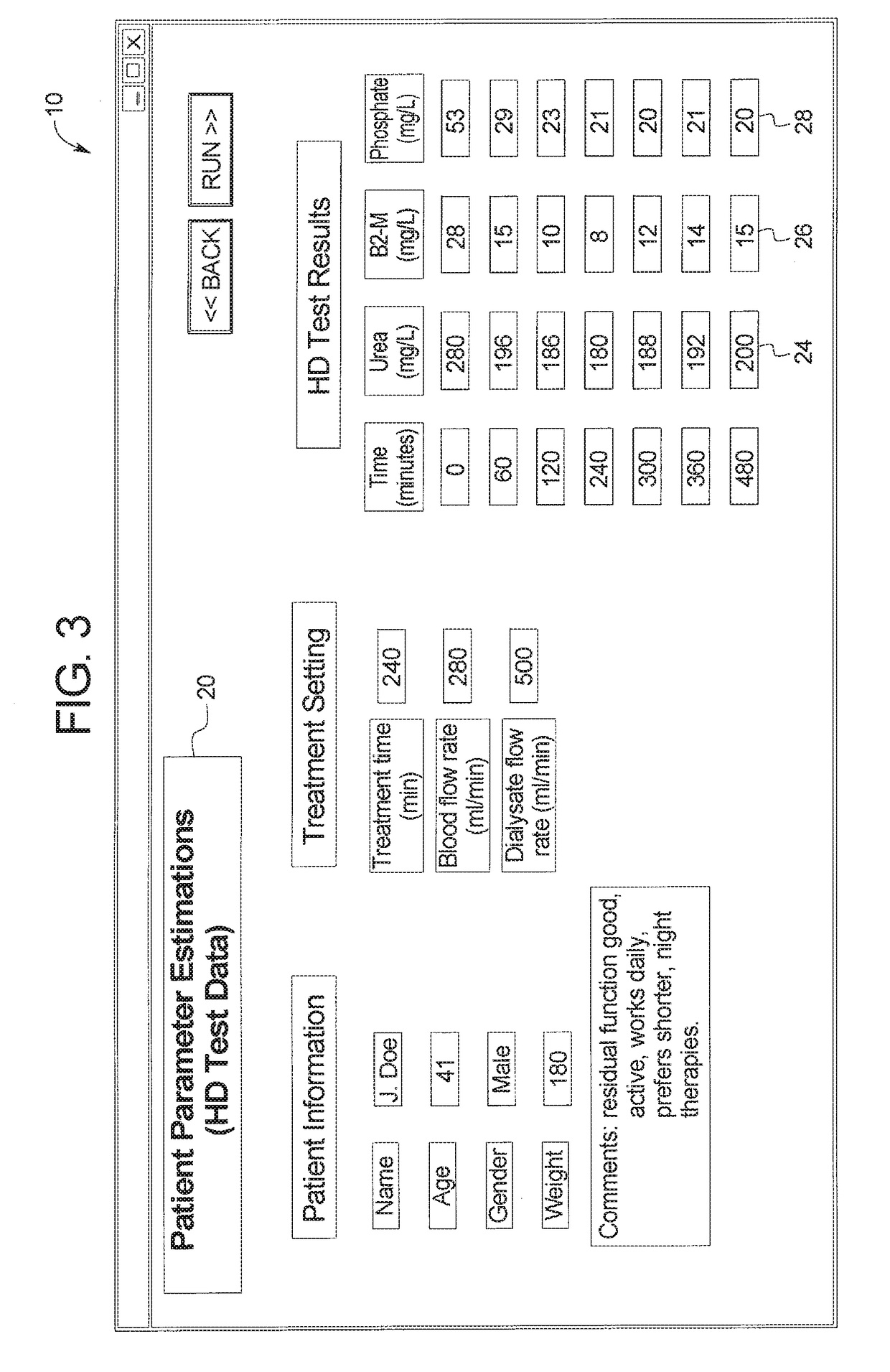
This patent is a system that predicts the level of certain substances in the body, like urea, β2-M, and phosphate, during dialysis treatment. The system uses the patient's parameters and other factors to estimate how well the treatment is going. This helps doctors create better treatment prescriptions for patients, which can lower costs and reduce the amount of dialysate needed. The system calculates the expected levels of these substances and helps doctors create personalized treatment sessions.

Problems solved by technology

That substitution fluid and the fluid accumulated by the patient in between treatments is ultrafiltered over the course of the HF treatment, providing a convective transport mechanism that is particularly beneficial in removing middle and large molecules (in hemodialysis there is a small amount of waste removed along with the fluid gained between dialysis sessions, however, the solute drag from the removal of that ultrafiltrate is not enough to provide convective clearance).
Home hemodialysis (“HHD”) has to date had limited acceptance even though the clinical outcomes of this modality are more attractive than conventional hemodialysis.

Method used


Image

  • Therapy prediction and optimization for renal failure blood therapy, especially home hemodialysis
  • Therapy prediction and optimization for renal failure blood therapy, especially home hemodialysis
  • Therapy prediction and optimization for renal failure blood therapy, especially home hemodialysis

Examples


example 1

Objective

[0179]The objective of this analysis was to demonstrate the non-linear least squares fitting procedure for estimating patient specific parameters (e.g., KM and VPRE) from a pseudo one-compartment model using clinical data, and to evaluate the validity of parameter estimates over different HD treatment modalities.

Pseudo One-Compartment Model

[0180]A conceptual description of the pseudo one-compartment model is shown in FIG. 11. In this model, phosphorus is removed by the dialyzer from a compartment of volume V, also called the distribution volume, and phosphorus concentration C. The distribution volume is assumed to be in equilibrium with plasma. Phosphorus mobilization into this compartment occurs from phosphorus pools in the body that are inaccessible to the dialyzer. These pools are represented as a large compartment with a constant phosphorus concentration equal to the pre-dialytic plasma phosphorus concentration (“CPRE”). The rate of phosphorus mobilization into the dist...

example 2

Objective

[0190]The objective of this study was to demonstrate the application of a simple method for estimating the patient parameter KM from a pseudo one-compartment model using data from conventional 4-hour hemodialysis treatments, and to evaluate the accuracy of estimated KM values via comparison to results obtained using non-linear least squares fitting.

Methods

[0191]Clinical data was obtained from 5 chronic hemodialysis patients who underwent CHD treatments. Blood samples were collected at t=0, 30, 60, 120, 180 min during the treatments and 10 seconds, 2, 10, 30, 60 min after the end of treatments. Dialysate samples were collected 60 min from the start of treatments to determine dialyzer phosphate clearance. Plasma and dialysate samples were assayed for phosphorus.

[0192]KM was computed for each patient using equation E-B1, where CPOST is the post-dialytic plasma phosphorus concentration, KD is the dialyzer phosphate clearance, QUF is the ultrafiltration rate or net fluid removal...

example 3

Steady State Phosphorus Mass Balance Model

Objectives

[0198]As previously discussed, the inventors have proposed a kinetic model for describing changes in serum or plasma phosphorus concentrations during hemodialysis (more generally extracorporeal treatments) and the post-dialytic rebound period. That kinetic model allows prediction of intradialytic phosphorus concentrations as a function of time and total phosphate removal from the knowledge of: 1) the pre-dialysis concentration of phosphorus in plasma or serum, 2) the dialyzer clearance of phosphate, 3) the volume of distribution of phosphorus, 4) the amount of fluid removed during the treatment, and 5) a patient-specific phosphorus mobilization clearance. The steady state phosphorus mass balance model described below will be used in combination with the previous kinetic model to allow determination of pre-dialysis serum phosphorus concentration for individual patients under any hemodialysis treatment prescription when the above par...


PUM


Abstract

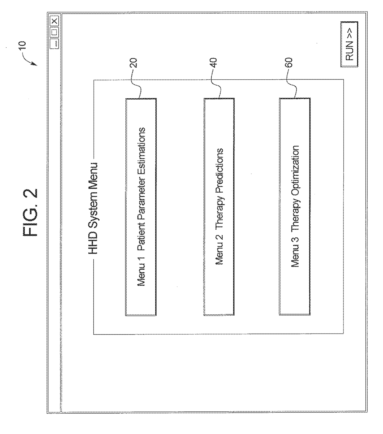
A renal failure blood therapy system includes a renal failure blood therapy machine, concentration levels for each of a plurality of solutes removed from a patient's blood at each of the multiple times, a display device configured to display for selection at least one removed blood solute from the plurality of removed blood solutes, and a device programmed to (i) estimate at least one renal failure blood therapy patient parameter using the determined concentration levels for the at least one selected removed blood solute, (ii) determine a plurality of acceptable renal failure blood therapy treatments that meet a predetermined removed blood solute clearance for the at least one selected removed blood solute using the at least one renal failure blood therapy patient parameter, and (iii) enable selection of at least one of the plurality of acceptable renal failure blood therapy treatments for operation at the renal failure blood therapy machine.

Description

PRIORITY CLAIM[0001]This application claims priority to and the benefit as a continuation application of U.S. patent application Ser. No. 14 / 472,757, filed Aug. 29, 2014, entitled “Therapy Prediction and Optimization for Renal Failure Blood Therapy, Especially Home Hemodialysis”, which claims priority to and the benefit as a continuation application of U.S. patent application Ser. No. 13 / 088,064, filed Apr. 15, 2011, entitled “Therapy Prediction and Optimization for Renal Failure Blood Therapy, Especially Home Hemodialysis”, now U.S. Pat. No. 8,845,570, issued Sep. 30, 2014, which claims priority to and the benefit of U.S. Provisional Patent Application Ser. No. 61 / 438,002 filed on Jan. 31, 2011, U.S. Provisional Patent Application Ser. No. 61 / 388,315 filed on Sep. 30, 2010 and U.S. Provisional Patent Application Ser. No. 61 / 325,113 filed on Apr. 16, 2010, the entire disclosures of each of which are hereby incorporated by reference and relied upon.BACKGROUND[0002]The present disclos...

Claims


Application Information

Patent Timeline
Patent Type & Authority Applications(United States)
IPC IPC(8): A61M1/16A61M1/36
CPCA61M1/1603A61M1/1611A61M1/3609A61M2205/3584A61M2205/502A61M2230/20A61M1/1613A61M2202/0498A61M2205/15A61M2205/52A61M1/1619A61M2205/50A61M1/16G16H20/40
Inventor AKONUR, ALPLEYPOLDT, JOHN KENNETHLO, YING-CHENGAGAR, BARIS UGUR
Owner BAXTER INT INC
Learn More