Exposure apparatus and method for manufacturing device

a manufacturing device and exposure apparatus technology, applied in the direction of microlithography exposure apparatus, printers, instruments, etc., can solve the problems of insufficient focus margin during exposure operation, surface undulation, pattern image projected onto the substrate deterioration, etc., to prevent the deterioration of the pattern image projected onto the substrate, suppress the scattering of liquid, and improve the movement accuracy of the substrate stage

Inactive Publication Date: 2006-02-16
NIKON CORP
View PDF91 Cites 25 Cited by
  • Summary
  • Abstract
  • Description
  • Claims
  • Application Information

AI Technical Summary

Benefits of technology

[0009] The present invention has been made in consideration of such situations, and its objective is to provide an exposure apparatus and a device manufacturing method in which scattering of the liquid for forming a liquid immersion region is suppressed, the movement of the substrate stage is not obstructed by pipings and the like for supplying and recovering the liquid, and a substrate can be exposed with a required pattern accuracy.
[0013] In accordance with the present invention, since the substrate moving device that is movable while holding the substrate is provided above the projection optical system, a liquid immersion region can be formed between the projection optical system and the substrate, with the liquid being held on the upper end portion of the projection optical system fixed at a predetermined position. That is, since it is configured such that the substrate moves relative to the liquid, scattering of the liquid can be suppressed, and deterioration of the pattern image projected onto the substrate can be prevented. In addition, since pipings and the like for supplying and recovering the liquid for forming the liquid immersion region on the upper end portion of the fixed projection optical system need not be connected to the substrate moving device (substrate stage), deterioration of the movement accuracy of the substrate stage due to the pipings and the like does not occur.

Problems solved by technology

When the depth of focus δ becomes too narrow, it becomes difficult to make the substrate surface coincide with the image plane of the projection optical system, and thus there occurs the possibility that the focus margin during the exposure operation will be insufficient.
By the way, with the above-mentioned related art, there are problems as described below.
In the case of such a configuration, when the substrate stage is moved, there arises not only the possibility that the liquid surface undulates and the liquid scatters, but also the possibility that the pattern image projected onto the substrate deteriorates due to the undulation of the liquid.
In addition, pipings for supplying and recovering the liquid need to be connected to the substrate stage, which may adversely affect the movement accuracy of the stage.

Method used


Image

  • Exposure apparatus and method for manufacturing device
  • Exposure apparatus and method for manufacturing device
  • Exposure apparatus and method for manufacturing device

Examples


Embodiment Construction

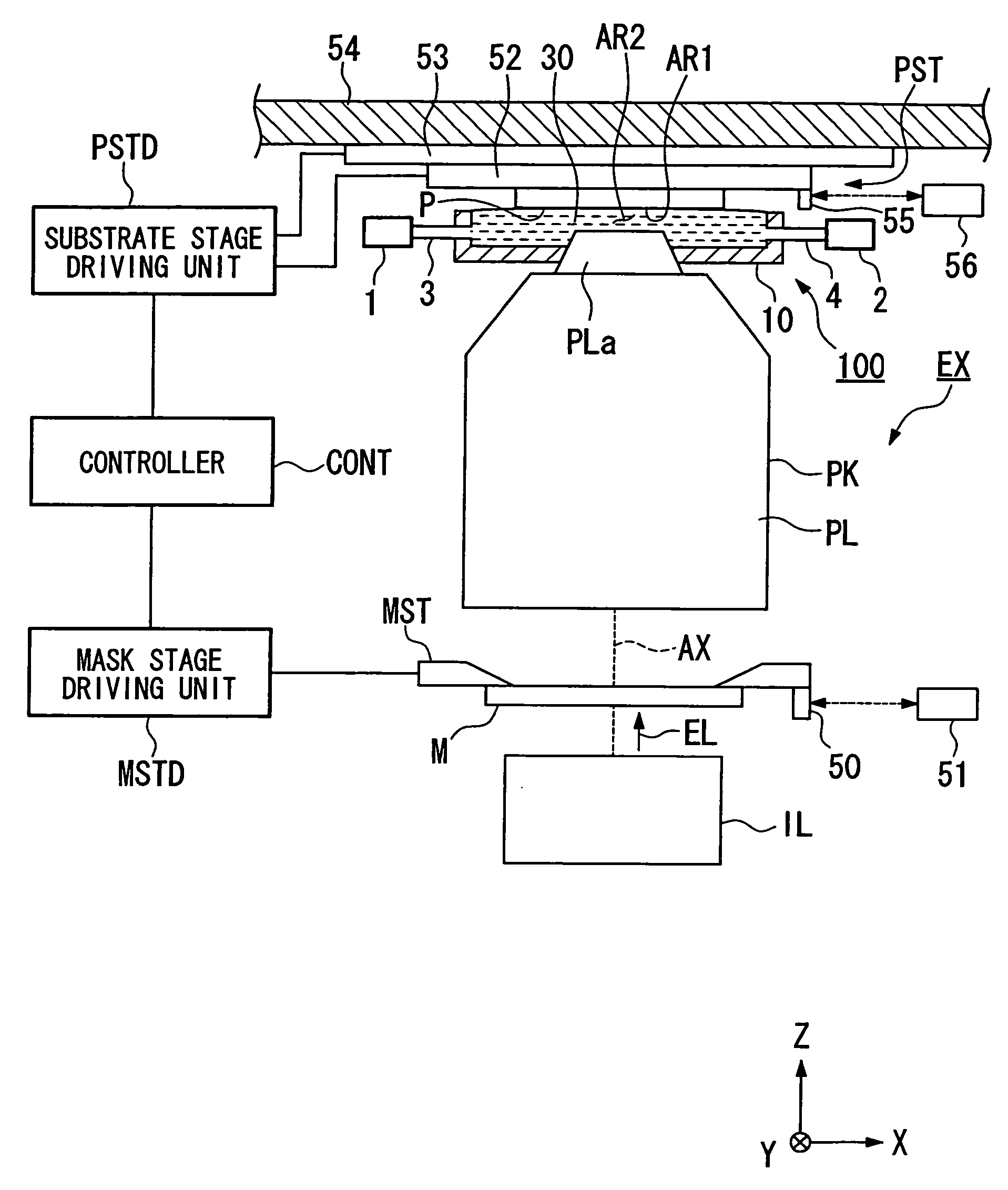
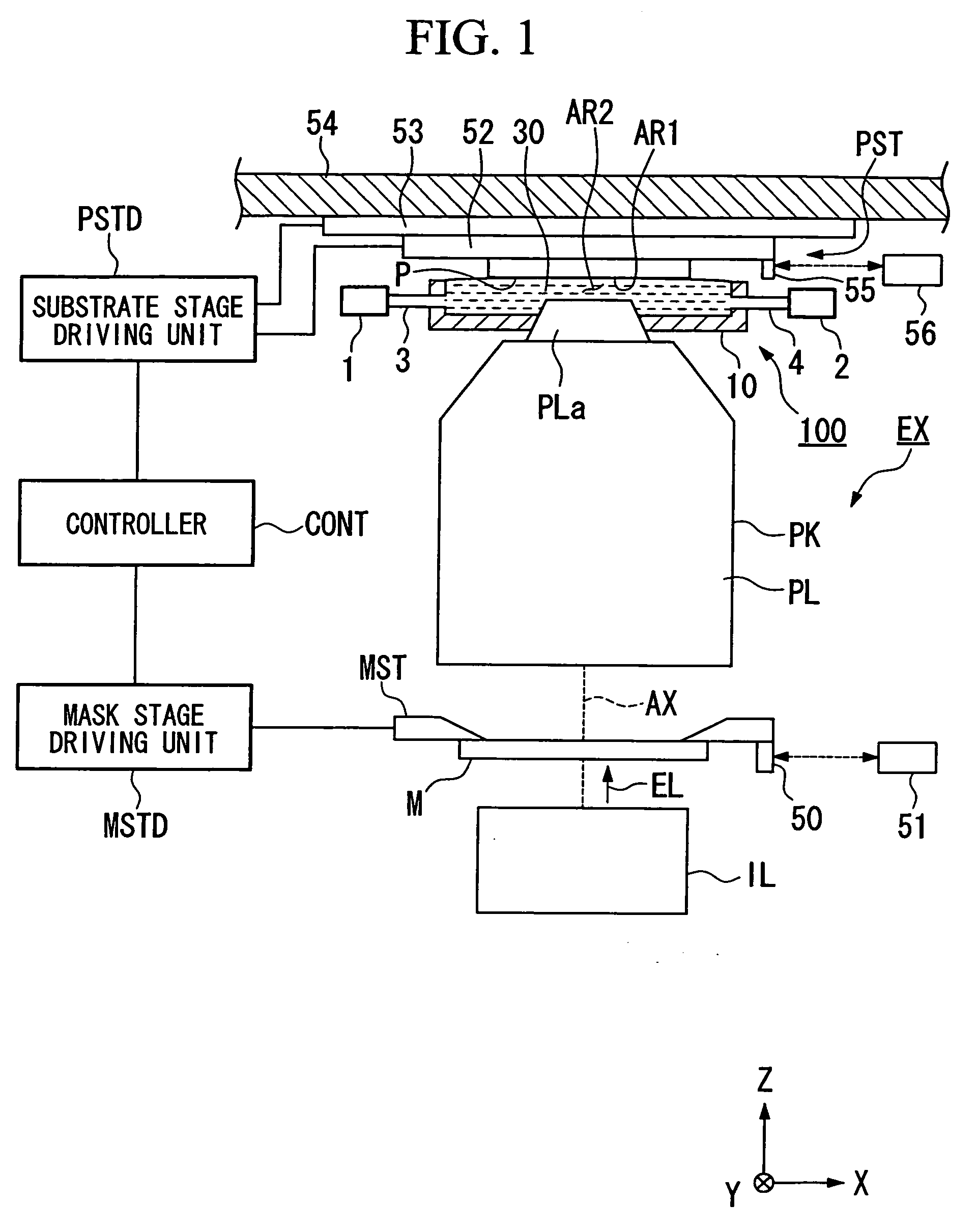
[0022] Now, referring to the drawings, an exposure apparatus of the present invention will be described. FIG. 1 is an outline configuration drawing showing a first embodiment of an exposure apparatus of the present invention.

[0023] Referring to FIG. 1, an exposure apparatus EX is provided with a mask stage MST that holds a mask M, a substrate stage PST that holds a substrate P, an illumination optical system IL that illuminates the mask M held by the mask stage MST with exposure light EL, a projection optical system PL that projects a pattern image of the mask M illuminated with the exposure light EL onto the substrate P held by the substrate stage PST, and a controller CONT that controls the overall operation of the exposure apparatus EX. The projection optical system PL is configured to form an image plane thereabove. The mask stage MST that holds the mask M is disposed under the projection optical system PL, and on the other hand, the substrate stage PST that holds the substrate...


PUM

PropertyMeasurementUnit
wavelengthaaaaaaaaaa
refractive indexaaaaaaaaaa

Abstract

An exposure apparatus wherein an image of a pattern is projected onto a substrate via a projection optical system to expose the substrate, includes: a substrate moving device that is movable while holding the substrate above the projection optical system; and a liquid immersion unit that fills at least a portion of the space between the projection optical system and the substrate with a liquid, wherein the image of the pattern is projected onto the substrate via the projection optical system and the liquid.

Description

CROSS-REFERENCE TO RELATED APPLICATION [0001] This is a Divisional of Application No. 11 / 239,402, filed Sep. 30, 2005, which is a Continuation Application of International Application No. PCT / JP2004 / 004969, filed Apr. 6, 2004, which claims priority to Japanese Patent Application No. 2003-103145, filed Apr. 7, 2003. The content of the aforementioned application is incorporated herein by reference.BACKGROUND OF THE INVENTION [0002] 1. Field of the Invention [0003] The present invention relates to an exposure apparatus and a device manufacturing method in which an image of a pattern is projection-exposed onto a substrate via a projection optical system and, in particular, to a liquid immersion type exposure apparatus. [0004] 2. Description of Related Art [0005] Semiconductor devices and liquid crystal display devices are manufactured through the so-called photolithography technique, by which a pattern formed on a mask is transferred onto a photosensitive substrate. The exposure apparat...

Claims


Application Information

Patent Timeline
Patent Type & Authority Applications(United States)
IPC IPC(8): G03B27/42G03F7/20
CPCG03F7/70341G03B27/42
Inventor HARA
Owner NIKON CORP
Why Eureka
Try Eureka