Magnetic disk drive, wiring connection structure and terminal structure

a technology of magnetic disk drive and wiring connection, which is applied in the direction of integrated arm assemblies, instruments, record information storage, etc., can solve the problems of increasing design and manufacturing difficulties of various parts of suspensions for moving magnetic heads, reducing size, etc., and achieves superior soldering function, enhanced strength of insulating layer, and improved productivity

Inactive Publication Date: 2006-02-16
WESTERN DIGITAL TECH INC
View PDF11 Cites 18 Cited by
  • Summary
  • Abstract
  • Description
  • Claims
  • Application Information

AI Technical Summary

Benefits of technology

[0010] The present invention has been accomplished for solving the above-mentioned conventional problems. It is a feature of the present invention to provide a highly reliable terminal structure and wiring connection structure able to improve productivity. It is another feature of the present invention to prevent cracking of terminals of a wiring trace in a head suspension assembly at the time of connecting terminals of a flexible printed circuit board with the terminals of the wiring trace and also prevent the addition of solder. It is yet another feature of the present invention to provide a magnetic disk drive using those terminal structure and wiring connection structure.
[0014] The present invention is an improved invention of a terminal structure and a wiring connection structure in connection with terminals formed in a wiring trace and connected to terminals of a flexible printed circuit board. A terminal formed in a conductor pattern of the wiring trace is provided with an exposed portion exposed from an aperture formed in part of an insulating layer and a lining portion adjacent to the exposed portion in a longitudinal direction of the conductor pattern and bonded to the insulating layer. According to this construction it is possible to form a highly reliable terminal structure. For example, at the time of heating the terminal of the wiring trace with a soldering iron in the conventional terminal structure, the terminal may be cracked if it is aligned with a terminal of a flexible printed circuit board or if it is displaced after soldering. In the terminal structure of the present invention, since the lining portion of the terminal is bonded to the insulating layer, the exposed portion is strengthened and difficult to be cracked. Even if the exposed portion should be cracked, there is no fear that the crack may reach the lining portion. Thus, the conductivity of the terminal is ensured. If a through aperture extending through an area of the insulating layer adjacent to the exposed portion in the longitudinal direction of the conductor pattern is formed in the aperture formed in part of the insulating layer, solder comes to connect a heating surface and a contact surface of the exposed portion with each other through the through aperture. Once the solder thus connects the heating surface and the contact surface of the exposed portion with each other through the through area of the insulating layer, the solder connection by the lapping of solder becomes stronger. The “lining portion adjacent to the exposed portion and bonded to the insulating layer” as referred to herein means that the exposed portion and the lining portion are in contact with each other adjacently and continuously.
[0016] The aspect just described above is concerned with conductor patterns having plural terminals, and since the portions of the insulating layer corresponding to the lining portions of the first and second conductor patterns are connected together at a foremost end portion of the wiring trace rather than the lining portions, the strength of the insulating layer may be enhanced around the aperture.
[0017] According to the present invention it is possible to provide a magnetic disk drive able to connect terminals of a flexible printed circuit board and terminals of a wiring trace in a head suspension assembly with each other by soldering without giving rise to any soldering defect, as well as a wiring connection structure and a terminal structure both used in the magnetic disk drive. According to the present invention, moreover, it is possible to provide a magnetic disk drive able to improve productivity and superior in soldering function, as well as a wiring connection structure and a terminal structure both used therein.

Problems solved by technology

With the recent tendency to the reduction in size of hard disk drives, the design and manufacture of various portions of a suspension for moving a magnetic head are becoming more and more difficult.

Method used


Image

  • Magnetic disk drive, wiring connection structure and terminal structure
  • Magnetic disk drive, wiring connection structure and terminal structure
  • Magnetic disk drive, wiring connection structure and terminal structure

Examples


Embodiment Construction

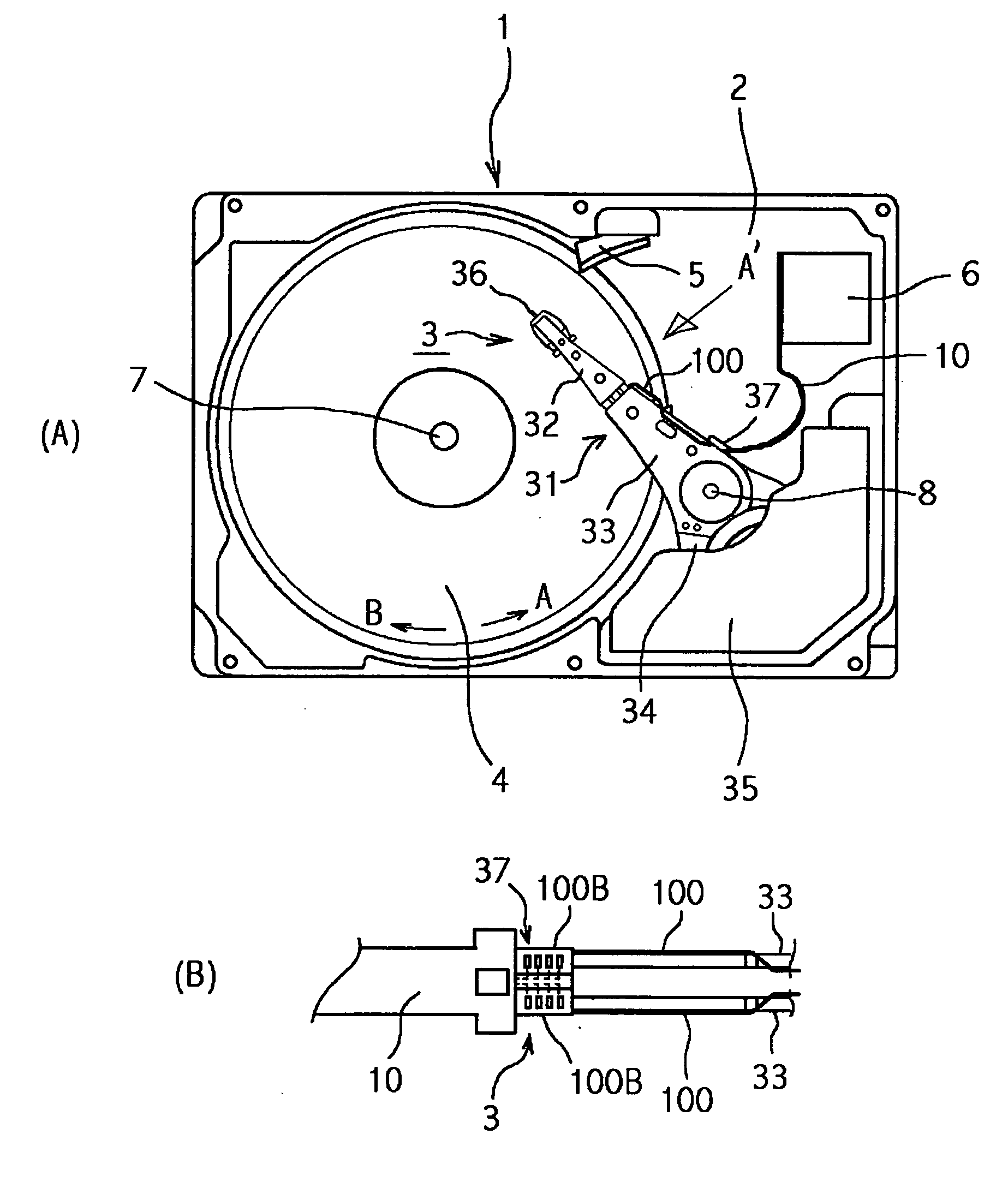
[0026] Embodiments of the present invention will be described hereinunder with reference to the drawings. In all of the drawings, like numerals indicate like elements. FIG. 1 illustrates a magnetic disk drive 1 according to an embodiment of the present invention, in which (A) is a plan view showing a schematic construction of the magnetic disk drive and (B) is a partially enlarged side view of an actuator head suspension assembly as seen in the direction of arrow A′ in (A). A base 2, together with a base cover (not shown), forms a hermetically sealed space. An actuator head suspension assembly 3, a magnetic disk 4, a ramp 5, and an external terminal 6 to be connected to a circuit board, are accommodated within the hermetically sealed space. The magnetic disk 4 is fixed to a spindle hub (not shown) so as to be rotated around a spindle shaft 7 by a spindle motor (not shown) disposed at a lower position. A magnetic layer is formed on at least one surface of the magnetic disk 4. Two or ...


PUM

PropertyMeasurementUnit
thicknessaaaaaaaaaa
thicknessaaaaaaaaaa
thicknessaaaaaaaaaa

Abstract

Terminals of a flexible printed circuit board and terminals of a wiring trace in a head suspension assembly are to be connected with each other by soldering without causing a soldering defect. In an embodiment, a terminal structure of a multi-connector in a wiring trace which includes an insulating layer and a conductor pattern portion formed on a surface of the insulating layer is provided with exposed portions of terminals exposed from apertures formed in part of the insulating layer and is also provided with lining portions adjacent to the exposed portions in a longitudinal direction of the conductor pattern portion and bonded to the insulating layer. Even if terminals of the multi-connector are cracked when soldered, not only conductivity is ensured, but also it is possible to strengthen the terminals, because the lining portions of the terminals are bonded to the insulating layer.

Description

CROSS-REFERENCES TO RELATED APPLICATIONS [0001] This application claims priority from Japanese Patent Application No. JP2004-231948, filed Aug. 9, 2004, the full disclosure of which is incorporated herein by reference. BACKGROUND OF THE INVENTION [0002] The present invention relates to a magnetic disk drive, as well as a wiring connection structure and a terminal structure in the magnetic disk drive. Particularly, the present invention is concerned with a terminal structure and a wiring connection structure both able to attain a stable electric connection between terminals of a flexible printed circuit board and terminals of a wiring trace in a head suspension assembly, as well as a magnetic disk drive using those terminal structure and wiring connection structure. [0003] With the recent tendency to the reduction in size of hard disk drives, the design and manufacture of various portions of a suspension for moving a magnetic head are becoming more and more difficult. In particular, ...

Claims


Application Information

Patent Timeline
Patent Type & Authority Applications(United States)
IPC IPC(8): G11B5/48
CPCG11B5/486H05K2201/09063H05K2201/0394H05K3/363G11B5/484G11B5/4846
Inventor DEGUCHI, TAKAAKIKATOH, TOSHIYUKIKIGUCHI, KATSUMISASAOKA, NOBUOSUZUKI, KOHICHITSUDA, SHINGO
Owner WESTERN DIGITAL TECH INC
Why Eureka
Try Eureka