

Method and apparatus for deblurring mask images
a mask image and mask technology, applied in the field of filters for improving the resolution of mask images, can solve the problems of reducing the size of the smallest defects that can be detected, affecting the quality of the mask image,
- Summary
- Abstract
- Description
- Claims
- Application Information
AI Technical Summary
Benefits of technology
Problems solved by technology
Method used
Image

Examples
Embodiment Construction
[0052] Reference will now be made in detail to preferred embodiments of the invention, examples of which are illustrated in the accompanying drawings. Wherever possible, the same reference numbers will be used throughout the drawings to refer to the same or like parts.
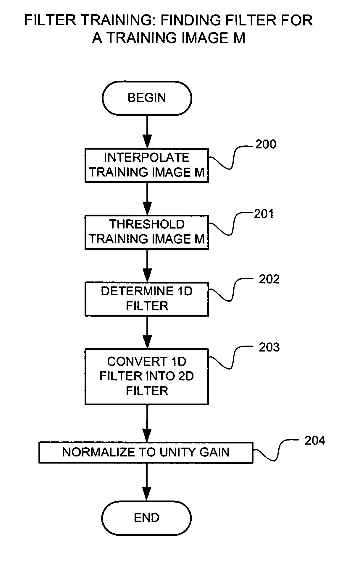
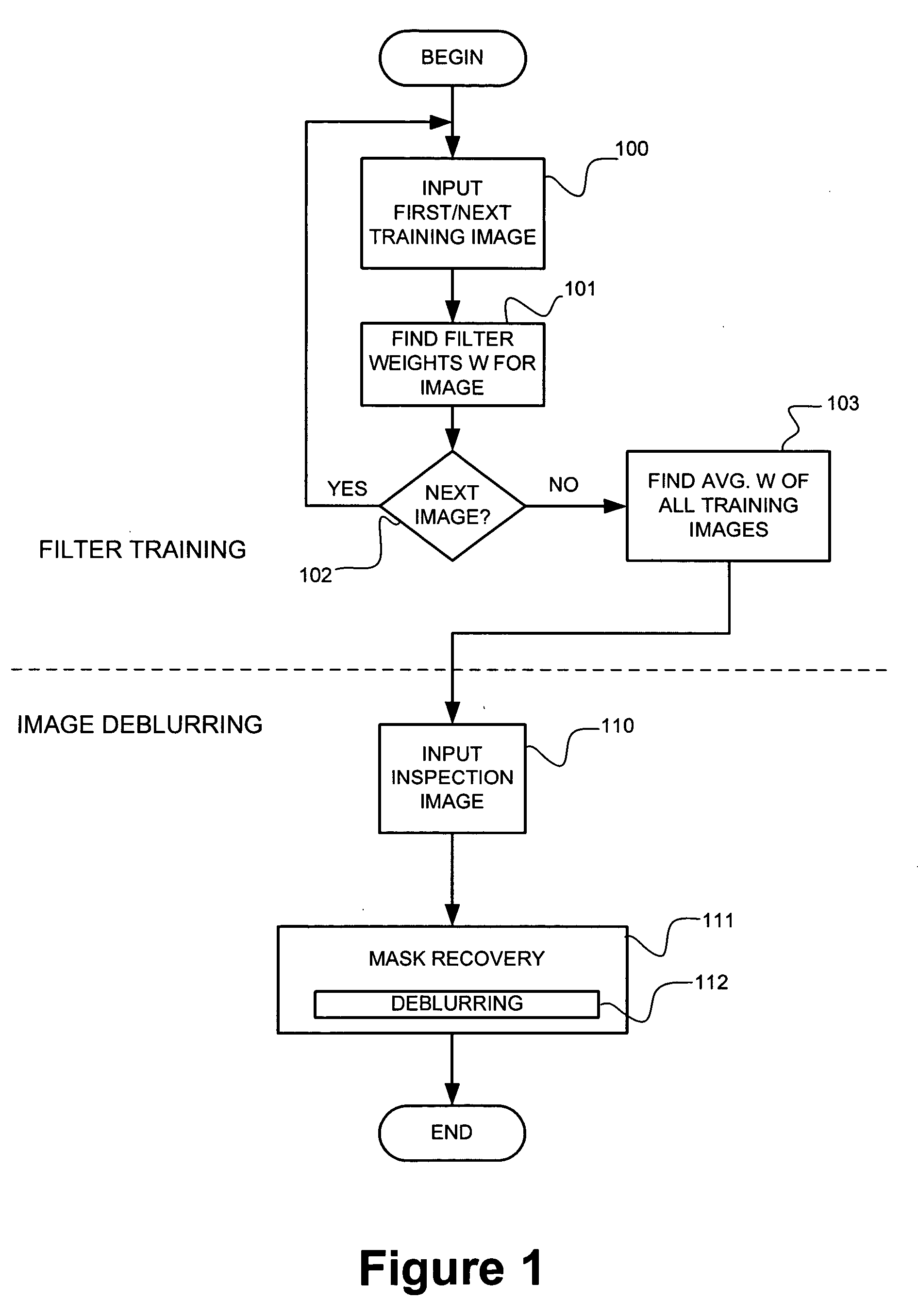
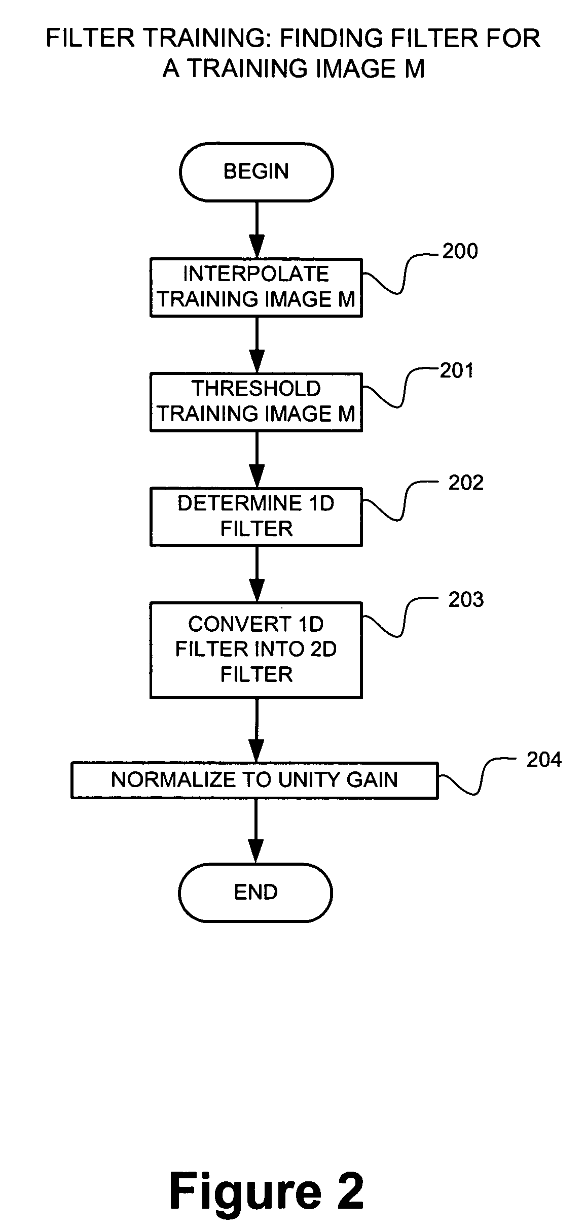
Table of Contents to Detailed Description1. Overview2. Further Details2.1 Interpolation2.2 Training Images2.3 One Dimensional Filter Determination2.4 One To Two Dimension Filter Conversion2.5 Image Deblurring2.6 Modified Approach: Separable Filter Training2.7 Training Image Recovery3. HARDWARE ENVIRONMENT
1. Overview
[0053] Deblurring, generally, is discussed in such texts as: A. K. Jain, “Fundamentals of Digital Image Processing,” Prentice Hall, Englewood Cliffs, N.J., 1989, ISBN 0-13-336165-9 (the Jain text). In particular, Chapter 8 of this text (pp.267-341) discusses “Image Filtering and Restoration.” The Jain text is herein incorporated by reference in its entirety.
[0054] The invention comprises processes for d...
PUM
 Abstract
Description
Claims
Application Information