Device and a method for removing an object from a moulding tool

a technology of moulding tool and object, which is applied in the field of methods for forming objects, can solve problems such as the risk of object deformation

Inactive Publication Date: 2006-02-16
COOL TOOL HLDG
View PDF7 Cites 12 Cited by
  • Summary
  • Abstract
  • Description
  • Claims
  • Application Information

AI Technical Summary

Benefits of technology

[0007] The object with the present invention is to provide a device assisting in releasing and removing objects from a moulding tool without causing any deformation of the object and thereby making it possible to remove the objects before they are entirely solidified.
[0008] This object is achieved by the initially mentioned device which is characterized in that it comprises a body, coupling means arranged for coupling the object to the body, and means for applying a traction force on the object, which is substantially opposite to said retaining force, wherein the body is designed with a contact surface adapted for at least partly being in contact with the object, and a coupling means is arranged to couple the object to the contact surface such that said traction force becomes substantially uniformly distributed over the part of the surface that is in contact with the contact surface. By distributing the traction force over as large a surface as possible, deformation of the surface of the object is avoided. The size and the shape of the contact surface determine how the traction power affects the device, and thereby the risk for deformation of the object. The larger the part of the surface of the object that is in contact with the contact surface is, the less the traction force per unit of area is, despite the fact that the total traction force on the object is still the same.
[0009] Thanks to the fact that the device can remove the object without substantially deforming the surface of the object, it is enough to keep the object in the moulding tool until the outer surface of the formed object is substantially form stable. Thus, it is possible to remove the object earlier and the cycle time at moulding or casting can be reduces in comparison with prior art. It is advantageous to use the device according to the invention in connection with the previously mentioned ejectors to remove the object. Thanks to the fact that the device applies a traction force on the object at the same time as the ejectors are pushing out the object, the ejectors do not necessarily have to push with as large a force as if they alone had to remove the object and thereby the risk for deformation of the object by the ejectors is reduced.
[0010] According to a preferred embodiment of the invention, the contact surface has a shape that is substantially adapted to the shape of the object. To distribute the forces over as large a part of the surface of the object as possible, it is advantageous if the contact surface has a shape that is substantially adapted to the shape of the object. It is an advantage if the contact surface has a shape that substantially is a reproduction of at least a part of the surface of any side of the formed object. The contact surface does not have to be an exact reproduction of the surface of the object; a rough reproduction it is enough. Depending on the shape of the object, the contact surface has to completely, or only partly, imitate the surface of the object. For a less complicated shape, it may be enough if the contact surface reproduces one or a few chosen parts of the object surface.
[0014] According to a further embodiment of the invention, it comprises at least one air-permeable contact means having a surface being at least a part of the contact surface and arranged to be in contact with the object in such a way that deformation of the object is counteracted. The contact means is arranged such that air is transported away from the contact surface to the coupling channel via the contact means. It is advantageous if the contact means is made of an substantially inelastic material. With such a contact means, it is possible to create an under-pressure between the contact surface and the object without deforming the surface of the object. If the coupling channel is connected directly to the contact surface, its entrance opening may cause deformation of the surface of the object, if the suction force is too large. Thanks to the fact that the contact means is arranged between the suction opening and the coupling channel, it is possible to increase the cross-section area of the coupling channel and the suction opening, which means that the suction force on the object can be increased without leading to deformation of the surface of the object.
[0016] According to a further embodiment of the invention, the contact means is arranged such that transportation of air from the contact surface to the coupling channel is performed through the contact means and that said sealing means is arranged so that it surrounds the contact means. To achieve an under-pressure between the contact surface and the object without risking that the yet not stable surface layer of the object becomes deformed, air from the contact surface is transported to the coupling channel via the contact means.

Problems solved by technology

The size and the shape of the contact surface determine how the traction power affects the device, and thereby the risk for deformation of the object.

Method used


Image

  • Device and a method for removing an object from a moulding tool
  • Device and a method for removing an object from a moulding tool
  • Device and a method for removing an object from a moulding tool

Examples


Embodiment Construction

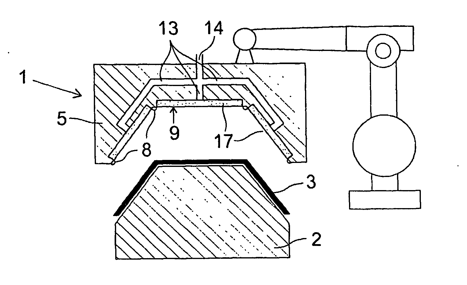
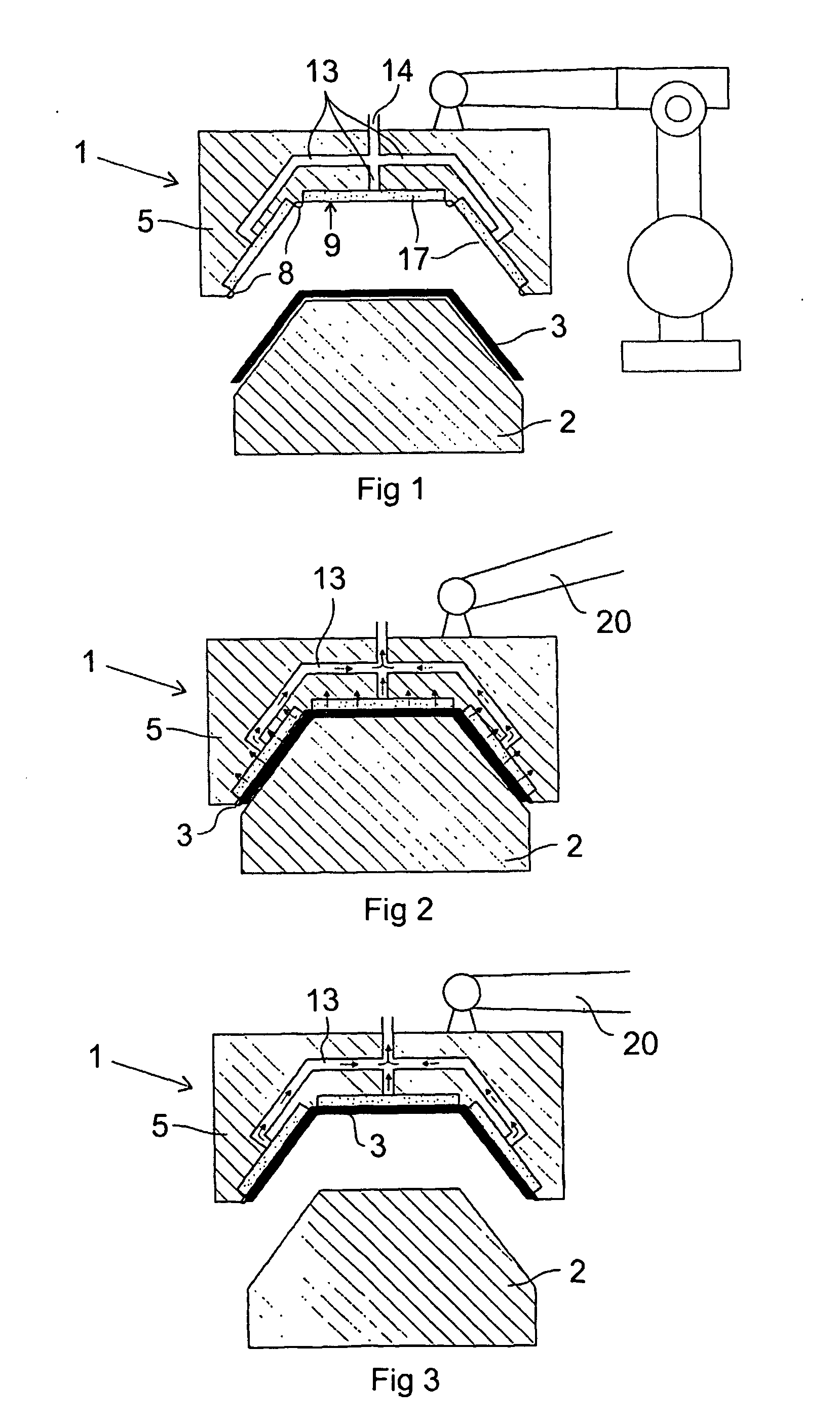
[0023] The FIGS. 1-3 show a device 1 according to the invention applied in a vacuum-moulding machine. The device 1 is arranged for removing an object from a moulding tool and then to transport the object away from the moulding tool without deforming the object. The vacuum-moulding machine comprises a moulding tool 2 having a surface, the shape of which determines the shape of the object to be mould. The source material to be mould is usually a sheet of a suitable plastic. The sheet is heated during the vacuum-moulding process so that it becomes soft and formable. When the sheet has reached the right temperature, a relative movement between the sheet and the moulding tool 2 occurs so that they get in contact with each other. Thereafter, the sheet is sucked towards the forming tool by means of under-pressure, so that the sheet is shaped after the surface of the moulding tool and the object 3 is formed. Cooling is performed in the moulding tool until the object becomes substantially fo...


PUM

PropertyMeasurementUnit
sizeaaaaaaaaaa
heightaaaaaaaaaa
traction forceaaaaaaaaaa

Abstract

A device (1) and a method for removing an object from a moulding tool (2) in connection with casting or moulding an object, wherein there is a retaining force between the moulding tool and the object The device comprises a body (5), coupling means (13) arranged for coupling the object to the body and means (20) for applying a traction force on the object, which is substantially opposite to said retaining force, wherein the body is designed with a contact surface adapted for at least partly being in contact with the object, and the coupling means is arranged to couple the object to the contact surfaces such that said traction force becomes substantially uniformly distributed over the part of the surface of the object that is in contact with the contact surface.

Description

TECHNICAL AREA [0001] The present invention relates to a device and a method for removing an object from a moulding tool in connection with casting or moulding an object, wherein there is a retaining force between the moulding tool and the object. [0002] Such a device may be used for removing objects in connection with different kinds of moulding and casting processes, for example injection moulding, vacuum forming, thermoforming, compression moulding, or blow moulding. PRIOR ART [0003] There are many known methods for forming an object. One category of forming methods have in common that they are based on a work-piece, which is heated until it becomes formable and is then formed by pressing the work-piece against a moulding tool having a surface of a shape, which determines the shape of the object to be formed. The work-piece is usually a sheet or a tube of plastic that is heated until it becomes soft enough to be formed. When the work-piece has reached the correct temperature, the...

Claims


Application Information

Patent Timeline
Patent Type & Authority Applications(United States)
IPC IPC(8): B29C45/40B25J15/06B29C37/00B29C39/36B29C41/42B29C45/42
CPCB25J15/0616B29C37/0003B29C45/4225B29C39/36B29C41/42B29C37/0007
Inventor WENNBERG, MIKAEL
Owner COOL TOOL HLDG
Why Eureka
Try Eureka