Window lifter rail

Inactive Publication Date: 2006-02-23
ARVINMERITOR GMBH
View PDF0 Cites 30 Cited by
  • Summary
  • Abstract
  • Description
  • Claims
  • Application Information

AI Technical Summary

Benefits of technology

[0006] The subject invention provides a window lifter rail with a pulley and a pulley cover wherein the pulley cover can be fastened to the window lifter rail in various positions. The advantages achieved with the invention are in particular that the window lifter rail can be flexibly adapted t

Problems solved by technology

This results in a decrease in production costs.
Moreov

Method used


Image

  • Window lifter rail
  • Window lifter rail
  • Window lifter rail

Examples


Example

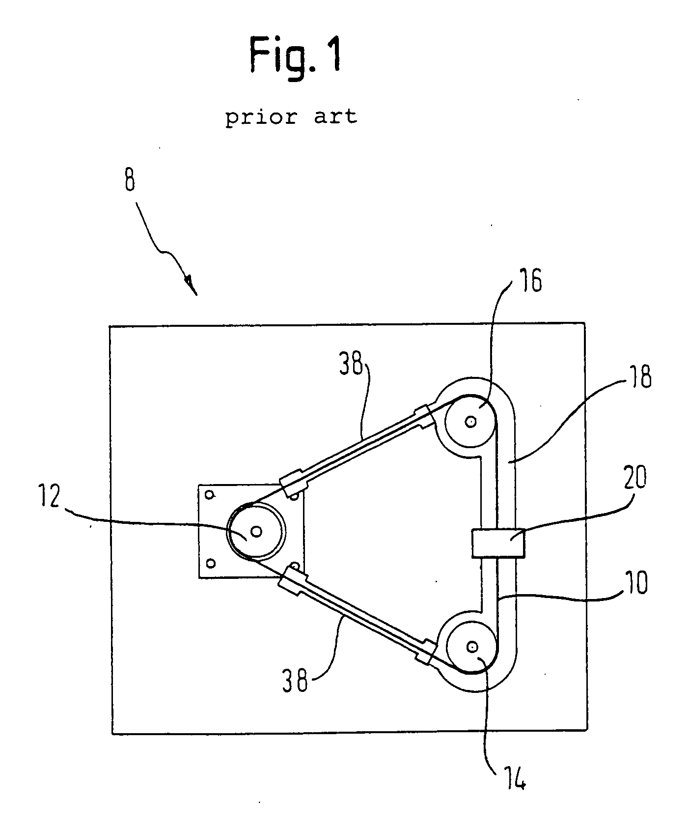
[0015]FIG. 1 schematically shows a traditional structure of a cable pull type window lifter 8. A tensile member 10 is wound around a cable drum 12 and is coupled by the cable drum 12 to a cable drive (not shown). The tensile member 10 is guided in a closed loop over a lower pulley 14 and an upper pulley 16. The lower and upper pulleys 14, 16 are fastened to a window lifter rail 18, and the tensile member 10 is provided with a sheathing at intermediate sections 38 between the lower and upper pulleys 14, 16 and the cable drum 12, if necessary. A driving dog 20 is connected with the tensile member 10 and with a window pane (not shown), so that the window pane can be moved upwards or downwards to a desired position by rotating the cable drum 12. The exact function of a cable pull type window lifter 8 will not be discussed here, since it is known from prior art and the invention related to deflection of the tensile member 10 in a region of the lower and upper pulleys 14, 16.
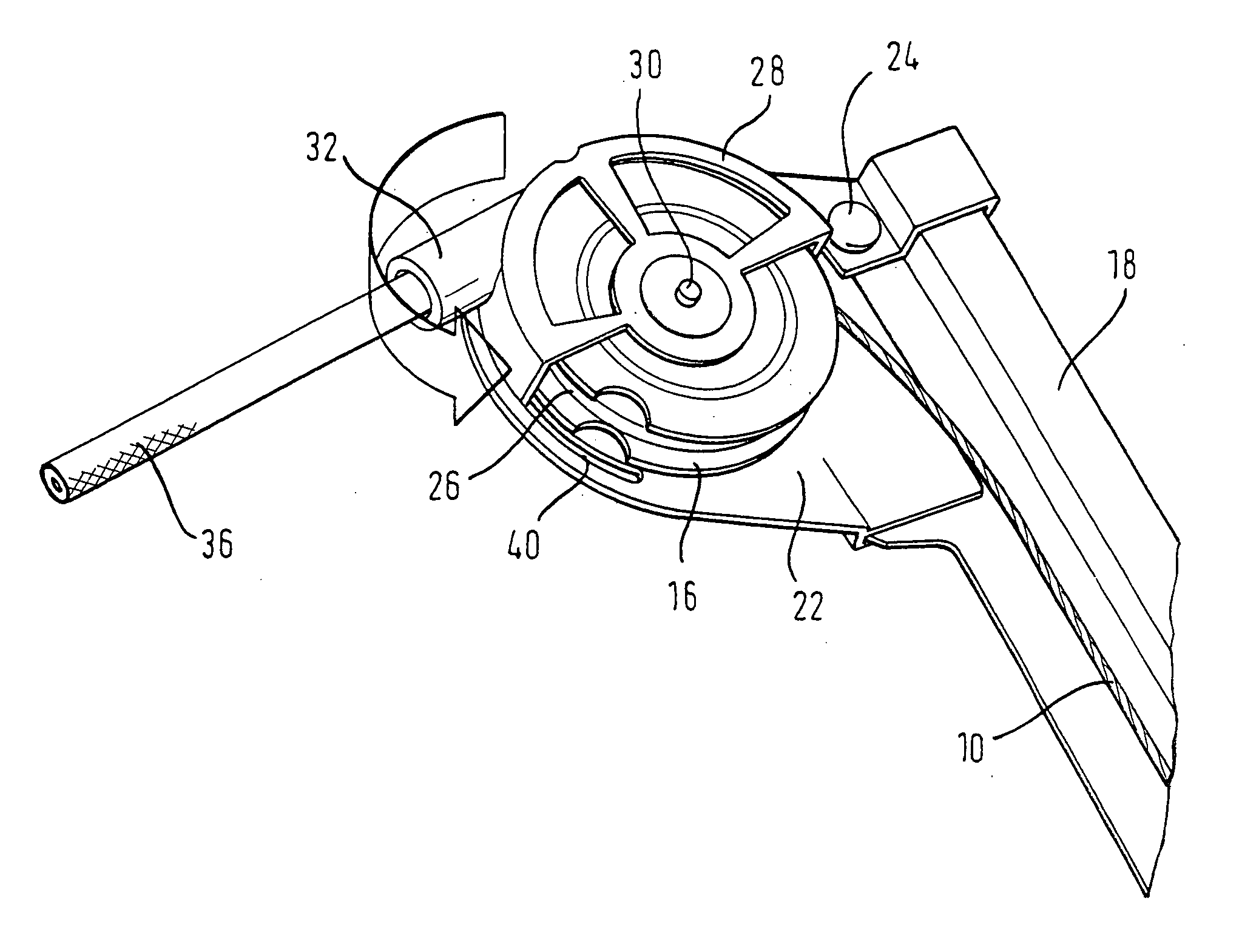
[0016]FIG. 2...


PUM


Abstract

A window lifter rail includes a pulley and a pulley cover. The pulley cover can be fastened to the window lifter rail in various positions. This ensures an assembly unit that offers a more flexible use while also reducing the production and installation costs.

Description

BACKGROUND OF THE INVENTION [0001] The application claims priority to German Application No. 10 2004 039 851.8, which was filed on Aug. 17, 2004. [0002] The invention relates to a window lifter rail comprising a pulley and a pulley cover. [0003] Window lifter rails with pulleys are used in cable pull type window lifters that lift and lower vehicle window panes. One known cable pull type window lifter includes a tensile member that is wound around a cable drum and several pulleys. In this arrangement, the pulleys are arranged on a window lifter rail, and the tensile member is connected to a driving dog. When the cable drum rotates, the driving dog is lifted and lowered and the window pane is moved to a desired position. [0004] Traditionally, window lifter rails include a rigid abutment that deflects the tensile member at an angle in a region of the pulleys. Different angles require different rigid abutments, such that each complete assembly unit for a respective operating condition h...

Claims


Application Information

Patent Timeline
IPC IPC(8): E05F11/48
CPCE05F11/483E05Y2201/11E05Y2201/654E05Y2900/55E05Y2201/668E05Y2600/53E05Y2201/662B60J1/12
Inventor HEYER, THOMASWAROCH, MARKUS
Owner ARVINMERITOR GMBH
Why Eureka
Try Eureka