Thermally-controlled actuator device

a technology of actuators and actuators, applied in the direction of couplings, cosmonautic components, cosmonautic parts, etc., can solve the problems of not always satisfying, not always enabling the part that is held stationary to be released, and the operation of known devices under particular conditions of acceleration, gravity, or weightlessness

Inactive Publication Date: 2006-02-23
ETIENNE LACROIX TOUS ARTIFICES
View PDF2 Cites 10 Cited by
  • Summary
  • Abstract
  • Description
  • Claims
  • Application Information

AI Technical Summary

Benefits of technology

[0009] The main object of the present invention is to propose a novel thermally-cont

Problems solved by technology

Nevertheless, it turns out that their operation under particular conditions of acceleration, gravity, or weightlessness, does not always give satisfaction.
The Applic

Method used


Image

  • Thermally-controlled actuator device
  • Thermally-controlled actuator device
  • Thermally-controlled actuator device

Examples


first embodiment

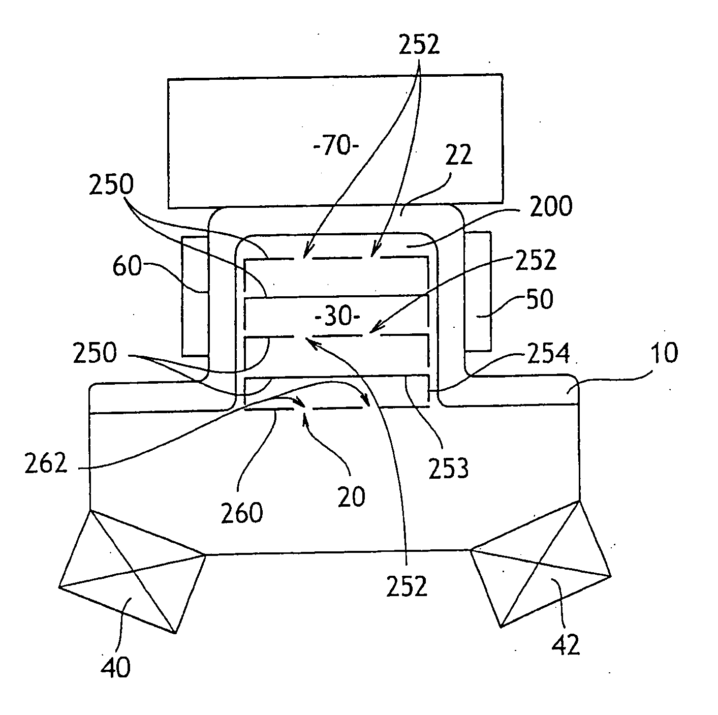
[0023] More precisely, in the present invention, shown in accompanying FIG. 2, the chamber 20 is constituted by a housing 200 formed in a main body 10 and subdivided by a plurality of disks or cups 250.

[0024] Still more precisely, in this embodiment, a plurality of cups 250 are preferably provided that are stacked at respective distances parallel to the end wall 22 of the chamber 20, together with a closure disk 260 which covers the outline of the opening of the chamber.

[0025] Typically, four cups 250 can thus be provided together with one disk 260. The disk 260 serves to “close” the chamber.

[0026] The section of each cup 250 and of the disk 260 is complementary to that of the chamber 20.

[0027] Each cup 250 is itself preferably constituted by a disk 253 carrying at its periphery a cylindrical collar 254 of height corresponding to the desired spacing between the cups 250.

[0028] Each cup 250 and the disk 260 preferably includes at least one through passage for transmitting initiat...

second embodiment

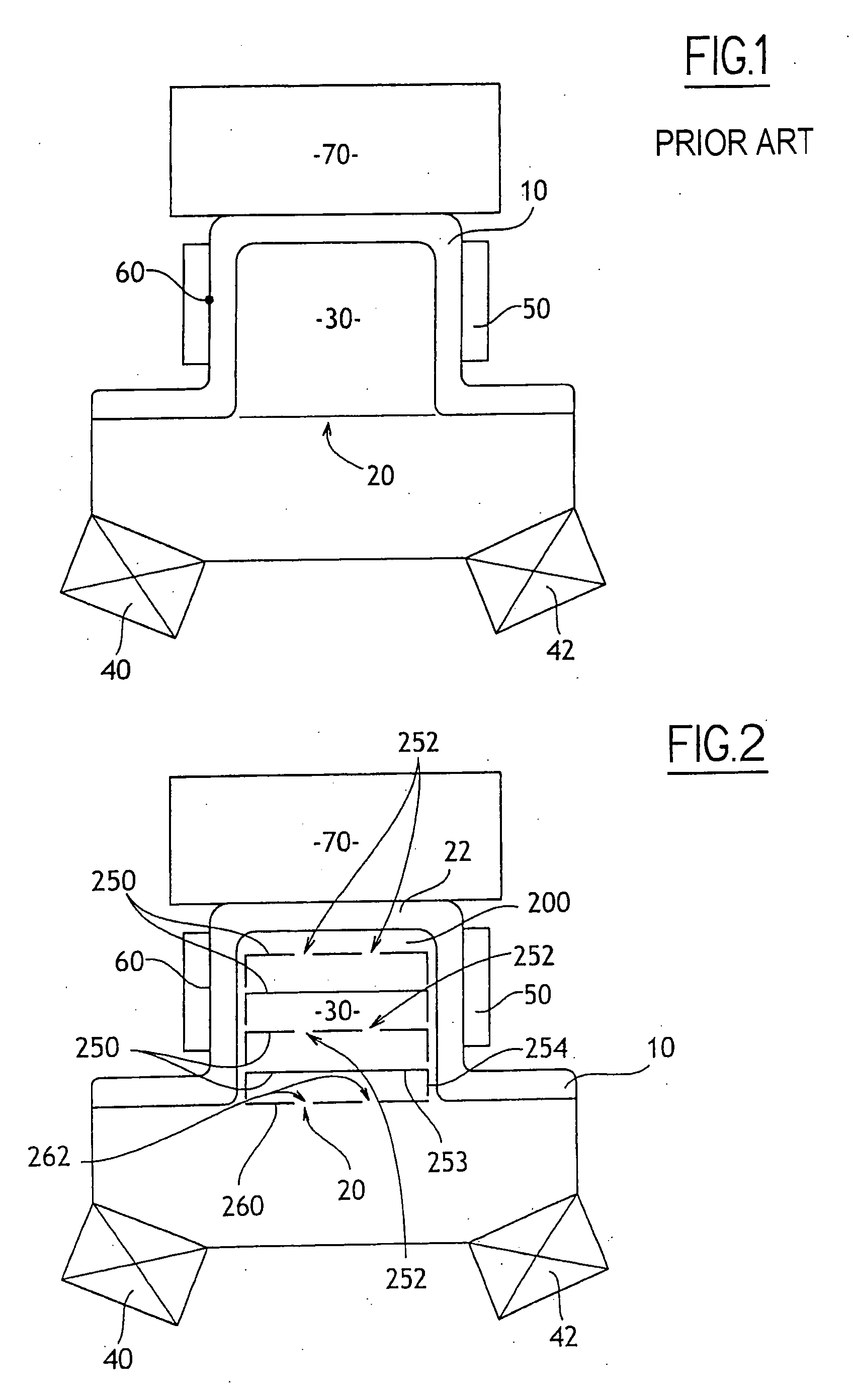
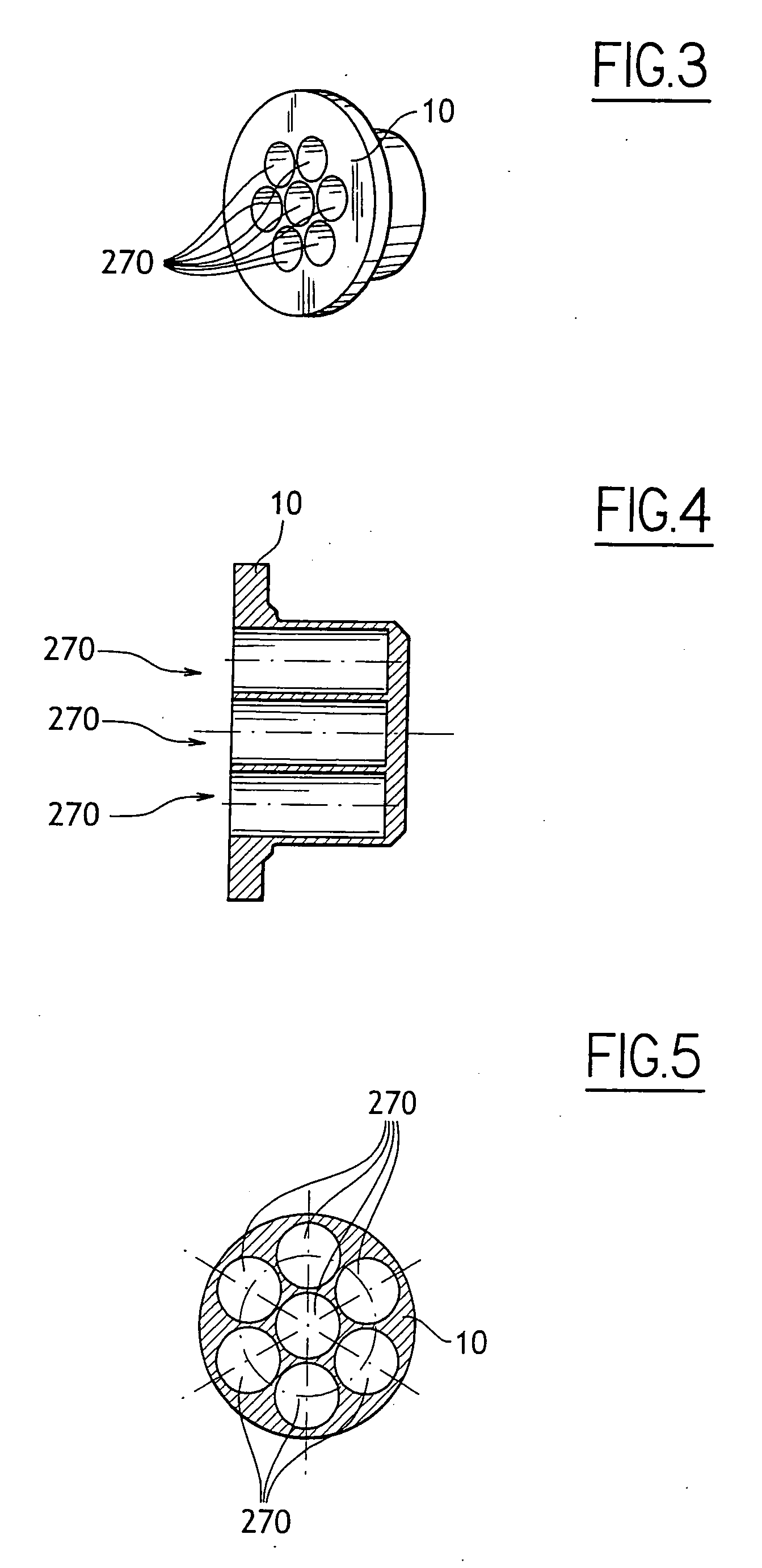
[0033] In the present invention, shown in FIGS. 3 to 5, the chamber 20 is formed by a plurality of blind wells 270 formed in the main body 10.

[0034] The body 10 may be made of any suitable material, for example stainless steel, titanium, or any equivalent material, such as a copper / tungsten mixture, e.g. Cu28 / W72.

[0035] Where appropriate, the wells 270 may be covered by a disk 260 like the disk shown in FIG. 2 and described above for the first embodiment.

[0036] Thus, accompanying FIGS. 3 to 5 show an embodiment of the present invention in which the chamber 20 is formed by seven wells each having a diameter of about 4.7 mm and a depth of about 11.5 mm (a central well is surrounded by a ring of six peripheral wells that are regularly distributed angularly) in a body of stainless steel that possesses an outside diameter of 16 mm and a height of 13.8 mm.

[0037] The ratio between the depth of a well 270 and its diameter is of the same order of magnitude as the ratio between the diamete...


PUM

PropertyMeasurementUnit
Diameteraaaaaaaaaa
Volumeaaaaaaaaaa
Volumeaaaaaaaaaa

Abstract

The present invention relates to a thermally-controlled actuator device of the type comprising a body, a part held stationary relative to the body by a low-melting point connection material, e.g. brazing or equivalent means, and a mass of exothermic material suitable for acting on command to give off intense heat energy suitable for melting the connection material so as to release the part relative to the body, wherein the exothermic material is housed in a chamber that is subdivided into a plurality of compartments suitable for confining said material in close thermal contact with the wall of the chamber.

Description

[0001] The present invention relates to the field of thermally-controlled actuator devices. [0002] More precisely, the present invention relates to the field of devices comprising a body, a part held stationary relative to the body by a low-melting point connection material, e.g. brazing or equivalent means, and a mass of exothermic material suitable for acting on command to give off intense heat energy suitable for melting the connection material so as to release the part relative to the body. BACKGROUND OF THE INVENTION [0003] Various devices of the above-specified type have already been proposed. [0004] An example of such devices is to be found in document FR-A-2 806 788. [0005] A particular application of the present invention lies in the aerospace domain, in particular for implementing a variety of equipments on satellites, such as deploying solar panels or releasing specific elements. [0006] Known devices of the above-specified type have already given good service. [0007] Neve...

Claims


Application Information

Patent Timeline
IPC IPC(8): B23K31/02B64G1/22B64G1/64F15B15/19F16D9/02
CPCB64G1/645B64G1/222
Inventor CRABOL, STEPHANEVALEMBOIS, GUYPOVEDA, PATRICK
Owner ETIENNE LACROIX TOUS ARTIFICES
Why Eureka
Try Eureka