Fluid cooled encapsulated microelectronic package

Active Publication Date: 2006-02-23
DELPHI TECH IP LTD
View PDF12 Cites 9 Cited by
  • Summary
  • Abstract
  • Description
  • Claims
  • Application Information

AI Technical Summary

Benefits of technology

[0003] The present invention is directed to a fluid cooled microelectronic package in which a fluid conducting cooling tube is directly coupled to one or more semiconductor chips and a plastic encapsulant is molded over the semiconductor chips and portions of the cooling tube i

Problems solved by technology

As a result, such cooling systems tend to be too large, too heavy and too expensive for many applications.
However, the packaging t

Method used


Image

  • Fluid cooled encapsulated microelectronic package
  • Fluid cooled encapsulated microelectronic package
  • Fluid cooled encapsulated microelectronic package

Examples


Example

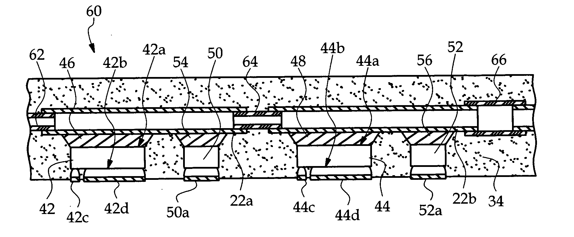
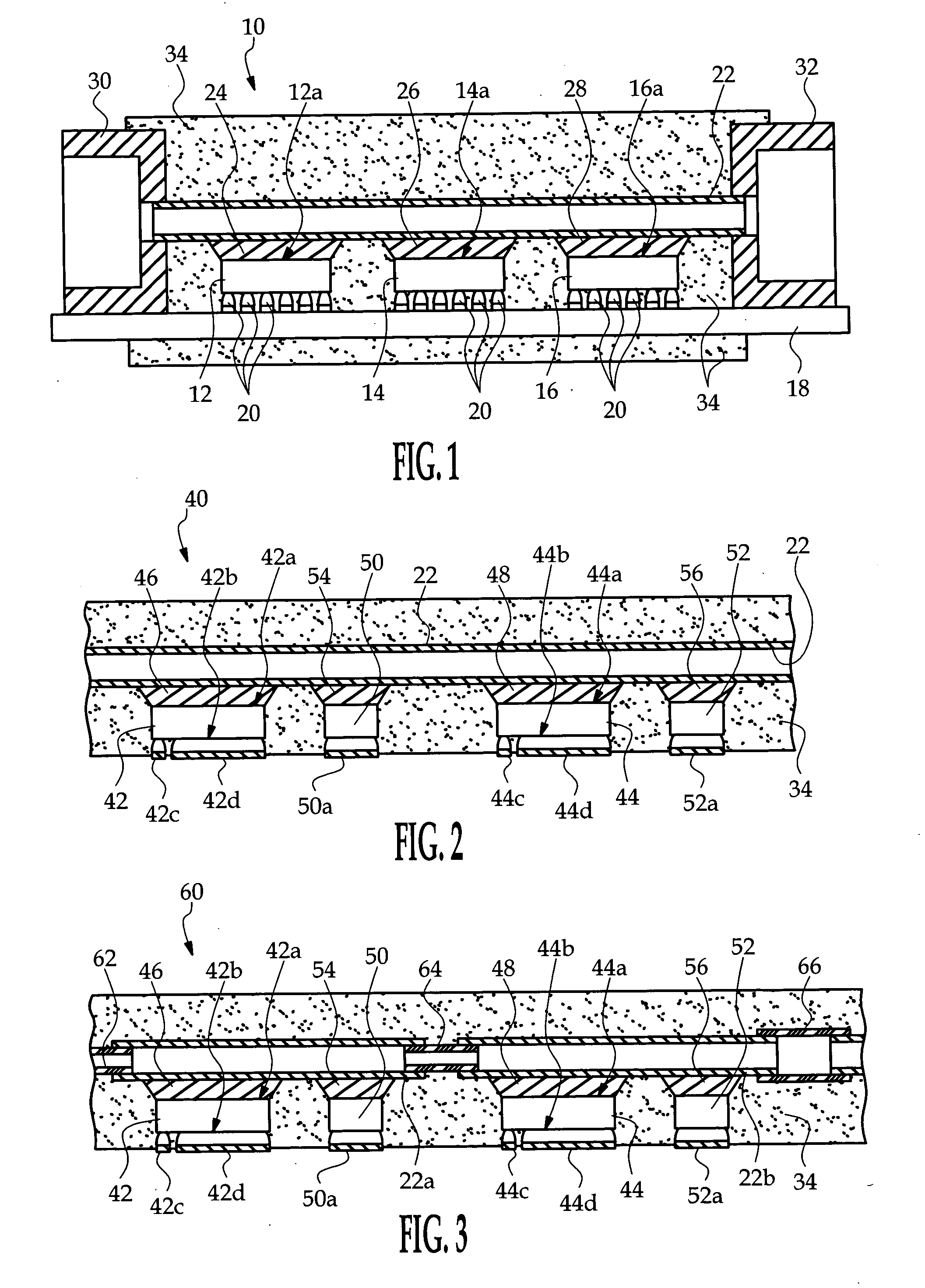
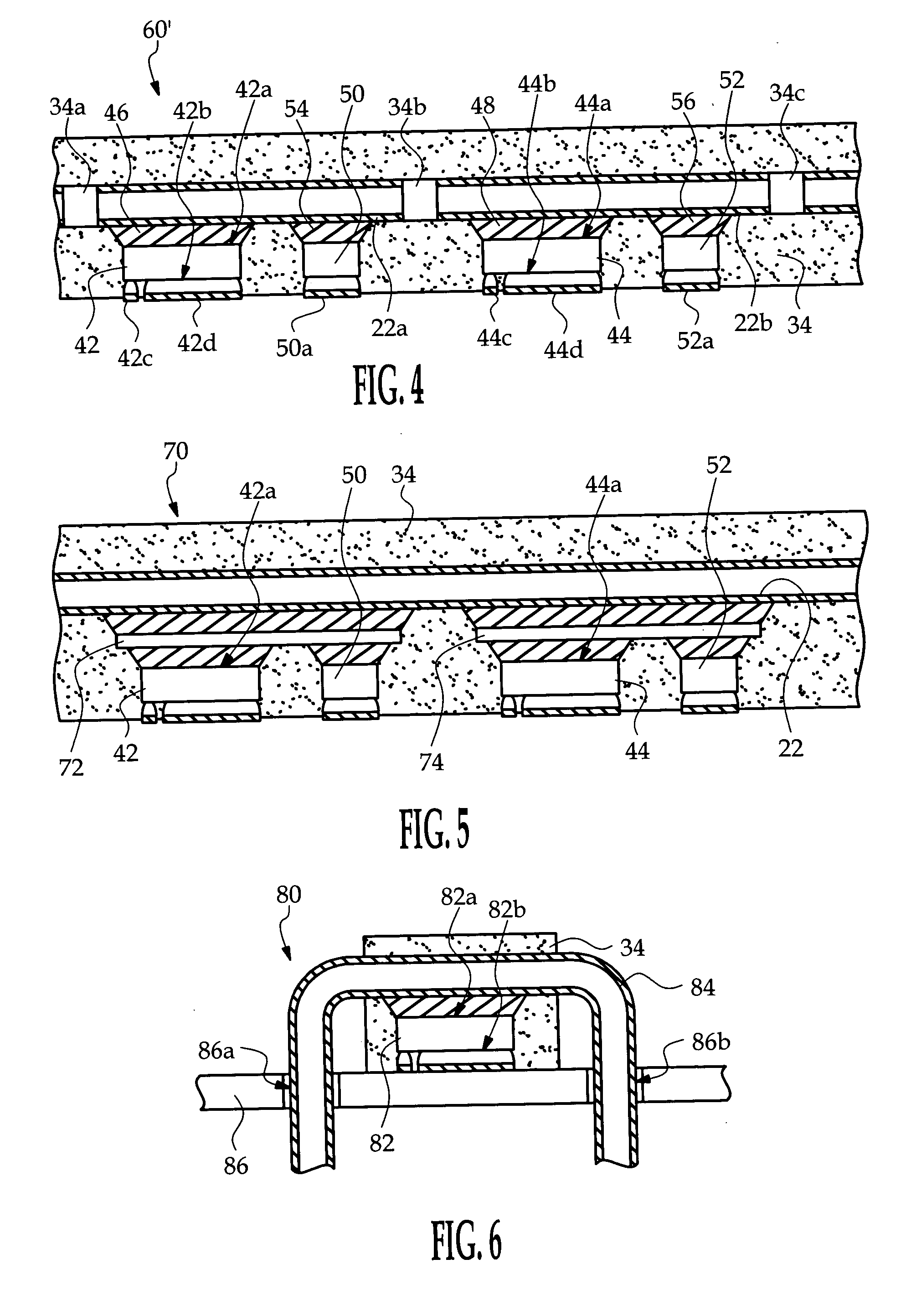
[0012] In general, the present invention is directed to fluid cooled microelectronic packages in which a fluid conducting cooling tube is coupled to one or more semiconductor chips and a plastic encapsulant is molded over the semiconductor chips and portions of the cooling tube in proximity to the semiconductor chips. As illustrated below, the cooling tube can be configured in different ways to accommodate lateral semiconductor chips having an exposed inactive surface or vertical semiconductor chips having an exposed active surface. In each case, the plastic encapsulant immobilizes the cooling tube with respect to the semiconductor chip to enhance reliability of the thermal joints, and the cooling tube and encapsulant are designed to minimize differences in their coefficients of thermal expansion relative to the semiconductor chip.

[0013] Referring to FIG. 1, the reference numeral 10 generally designates a liquid cooled encapsulated microelectronic package according to a first embod...


PUM


Abstract

An encapsulated microelectronic package includes a fluid conducting cooling tube directly coupled to one or more semiconductor chips, with the encapsulant being molded over the semiconductor chips and portions of the cooling tube in proximity to the semiconductor chips. The encapsulant immobilizes the cooling tube with respect to the semiconductor chips, and the cooling tube and encapsulant are designed to minimize differences in their coefficients of thermal expansion relative to the semiconductor chips.

Description

TECHNICAL FIELD [0001] The present invention relates to fluid cooling of microelectronic packages, and more particularly to an encapsulated microelectronic package having integral fluid cooling. BACKGROUND OF THE INVENTION [0002] Various types of cooling mechanisms can be used to remove waste heat from high power semiconductor devices, with liquid cooling being used in cases where the waste heat and / or the ambient temperature are very high. In a typical liquid cooling application, the microelectronic devices are mounted on a heat exchanger or cold plate that has internal fluid conducting channels and inlet and outlet pipes for coupling it to a cooling system including a fluid reservoir, a pump and an external heat exchanger. Due to limited thermal conduction between the semiconductor devices and the cold plate, the cold plate must be relatively large and the pump must be capable of producing high fluid flow. As a result, such cooling systems tend to be too large, too heavy and too e...

Claims


Application Information

Patent Timeline
IPC IPC(8): H01L23/34
CPCH01L23/473H01L2224/16H01L2224/73253H01L2924/13091H01L2924/13055H01L2924/00H01L2924/00014H01L2924/00011H01L2224/0401
Inventor BRANDENBURG, SCOTT D.CHENGALVA, SURESH K.DEGENKOLB, THOMAS A.
Owner DELPHI TECH IP LTD
Why Eureka
Try Eureka