System and method for optimizing motor performance by varying flux

a technology of flux and motor performance, applied in the direction of control system, dc motor speed/torque control, electrical apparatus, etc., can solve the problems of reducing the efficiency of the motor at lower speeds, and the use of very sensitive and expensive sensors for vector control algorithms to measure the operation of the motor, etc., to achieve the effect of efficient operation

Inactive Publication Date: 2006-02-23
PATENT
View PDF68 Cites 37 Cited by
  • Summary
  • Abstract
  • Description
  • Claims
  • Application Information

AI Technical Summary

Benefits of technology

[0008] A method for controlling an electric motor includes generating a voltage or current control signal in response to the speed (rotational frequency) of the electric motor and the current usage of the motor wherein the voltage control signal represents an efficient operating mode of the motor. Furthermore, a frequency control s...

Problems solved by technology

However, the efficiency of the motor is decreased at lower speeds when operated in the over-voltage condition.
In th...

Method used


Image

  • System and method for optimizing motor performance by varying flux
  • System and method for optimizing motor performance by varying flux
  • System and method for optimizing motor performance by varying flux

Examples


Embodiment Construction

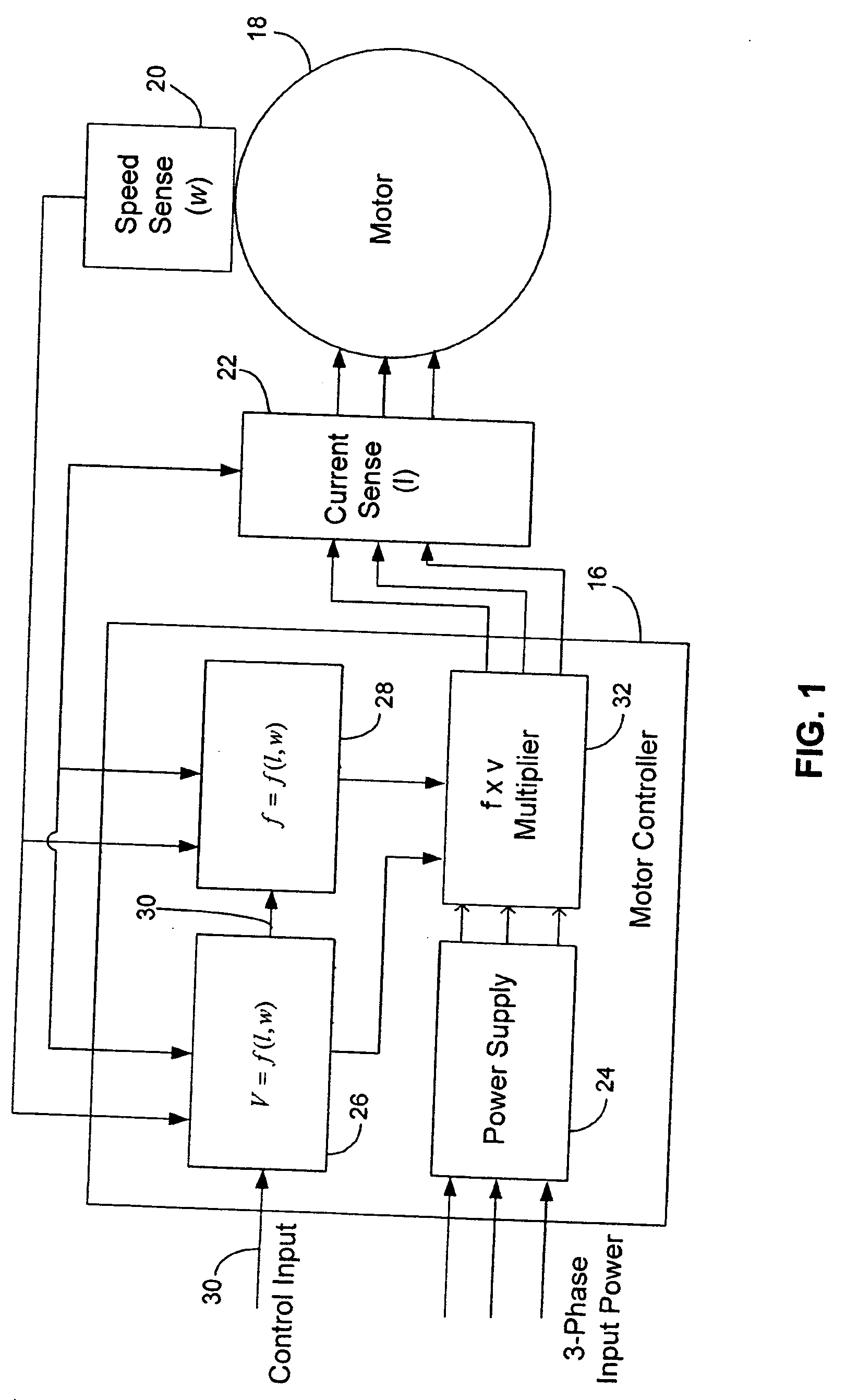
[0019] Referring now to the drawings wherein the showings are for purposes of illustrating preferred embodiments, and not for purposes of limiting the same, FIG. 1 is a block level diagram of a motor controller 16 used to control the operation of a 3-phase AC induction motor 18. The motor 18 may be a conventional AC induction type motor, or a motor operative with an increased stator / rotor air gap as described by Assignees co-pending patent applications Ser. No. 10 / 821,797, (Attorney Docket No. 146962-900002) and Ser. No. 10 / 894,688, (Attorney Docket No. 146962-999006), the contents of which are incorporated herein by reference.

[0020] The load of the motor is determined with a speed sense 20 and a current sense 22. Specifically, the speed sense 20 measures the rotational speed (w) of the motor 18 through either a sensor or sensor-less detection mechanism, as is commonly known and described in U.S. Pat. No. 5,600,218 entitled SENSORLESS COMMUTATION POSITION DETECTION FOR BRUSHLESS MO...


PUM


Abstract

A system for operating an electric motor is described. The system has a torque estimator to determine a load on the motor and a controller configured to generate a motor control signal. The controller continuously adjusts the motor control signal in response to the load on the motor. The motor control signal optimizes the motor's performance by controlling the rotor flux of the motor. The motor control signal can control the voltage or current and frequency applied to the motor.

Description

RELATED APPLICATION [0001] This application is a continuation-in-part of U.S. patent application Ser. No. 10 / 885,103 filed Jul. 7, 2004, the contents of which are incorporated by reference herein.FIELD OF THE INVENTION [0002] The present invention generally relates to controllers for electric motors and more specifically to a controller which can vary the voltage and frequency of the power applied to the motor in order to obtain maximum efficiency at any load. BACKGROUND OF THE INVENTION [0003] Controllers for electric motors provide electrical energy to the motor for proper operation. Typically, the controller applies a voltage or current to the motor at a prescribed frequency. The voltage and frequency are chosen to optimize the speed and torque output of the motor. [0004] It has been shown that with an AC induction motor, the torque output of the motor can be improved if an over-voltage condition is applied. During this condition, the motor is operated in a partial saturation con...

Claims


Application Information

Patent Timeline
IPC IPC(8): H02P7/42H02P27/00H02P23/00
CPCH02P23/14H02P23/0036H02P23/0004
Inventor HOLLING, GEORGE
Owner PATENT
Why Eureka
Try Eureka