
Method and probe for compensating for magnetic noise fields in space volumes, particularly in magnetic resonance imaging apparatus

Active Publication Date: 2006-02-23
ESAOTE
View PDF5 Cites 11 Cited by
  • Summary
  • Abstract
  • Description
  • Claims
  • Application Information

AI Technical Summary

Benefits of technology

[0021] This arrangement allows to partly compensate for the condition of saturation of a noise field probe by the magnetic field existing in the space volume. Therefore, the probe and the noise field detection locations may be closer to the space volume. In a MRI apparatus, this means that the probes may be closer to the magnet structure of the MRI apparatus and to the patient cavity and to the imaging volume. By at least partly compensating, at probe locations, for the static magnetic field induced by the magnet structures of such apparatuses on noise field probes, the saturation effect on such probes may be reduced, and probes may be restored to an operating condition, in which the strength of noise fields generated outside the MRI apparatus may be measured.
[0082] The use of gradient coils may be advantageous to compensate for noise fields which cause field in homogeneities within the imaging cavity of the Magnetic Resonance imaging apparatus. It shall be noted that this is indeed possible thanks to the fact that the compensation device is closely integrated in the Magnetic Resonance imaging apparatus. This close integration, whereby almost all the components of the compensation device, except the probes, are existing units of the Magnetic Resonance imaging apparatus, allows to operate and control even the gradient coils, with no expensive construction requirement, by setting the gradient field in such a manner as to compensate for any noise field-induced in homogeneity.

Problems solved by technology

Currently, the wide use of electric power causes the generation of considerable magnetic fields, which pervade the environment.
These magnetic fields may have considerable strengths and affect or alter the operation of electric or electronic equipment which use magnetic fields.
In these conditions, the calculation or determination of noise fields in the space volume are relatively complex and actually inaccurate.
For instance, when a chamber-like Faraday cage is provided, or when the Faraday cage is the MRI apparatus installation room itself, suitably having shielded walls, the probes shall be placed outside the Faraday cage, whereby they do not consider the shielding effect of the cage and the calculation or empiric determination of noise fields in the imaging volume of the MRI apparatus is even more complex and difficult, therefore more inaccurate.
Ignoring this phenomena would lead in a non correct reduction of the saturation of the probe and also to a non correct compensation of the effects of the noise fields in the space volume which is represented by the cavity of the MRI scanner defined by the magnetic structure.
These distances are relatively important and probes are unavoidably located outside the shielding chambers of MRI apparatuses or outside appropriately shielded rooms.

Method used


Image

  • Method and probe for compensating for magnetic noise fields in space volumes, particularly in magnetic resonance imaging apparatus
  • Method and probe for compensating for magnetic noise fields in space volumes, particularly in magnetic resonance imaging apparatus
  • Method and probe for compensating for magnetic noise fields in space volumes, particularly in magnetic resonance imaging apparatus

Examples


Embodiment Construction

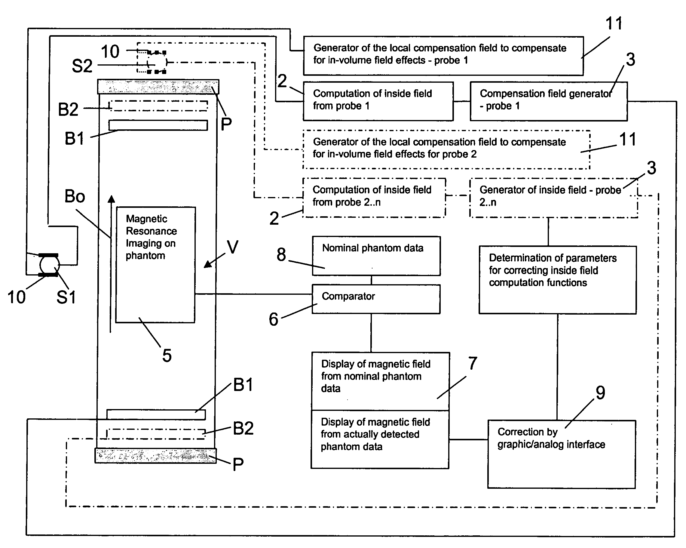
[0103] Referring to FIG. 1, a device for compensating for magnetic noise fields in a space volume V, like the imaging volume of the cavity for receiving the patient or a part of the patient body, of a Magnetic Resonance Imaging apparatus, has at least one probe S1 for measuring noise fields, which is placed outside the space volume V.

[0104] The probe S1 may be of any type, such as a small Hall probe or a small coil, or the like. The probe S1 is connected to a processing and compensation field generator unit, which includes a unit for computing or correlating the values of the noise field inside the space volume V on the basis of the noise field values detected by the probe S1 outside the space volume V. This unit performs the calculation and / or correlation operations by using theoretical or empirical functions, i.e., deriving from the laws of electromagnetism and / or from experiments.

[0105] The computation or correlation unit 2 may be a hardware unit which permanently incorporates ...


PUM


Abstract

A method for compensating in a space volume for a magnetic noise field outside the space volume includes determining a strength of the magnetic noise field outside the space volume; defining a correlation between the noise field outside the space volume and a corresponding noise field inside the space volume, or calculating the noise field inside the space volume on the basis of the measurements of the magnetic field outside the space volume; based on the noise field inside the space volume, generating a magnetic compensation field for neutralizing the noise field inside the space volume; wherein the compensation of the magnetic noise field outside the space volume is carried out along a direction in the space volume which is variable by determining a noise field component inside the space volume along the direction and generating a compensation field of the noise field component along the direction.

Description

CROSS-REFERENCE TO RELATED APPLICATIONS [0001] The present application claims the priority of Italian Patent Application Number SV2004A000032, filed on Aug. 5, 2004, the entire content of which is hereby incorporated herein by reference. FIELD OF THE INVENTION [0002] The invention relates to a method for compensating magnetic noise fields in space volumes, which space volumes are permeated by a magnetic field having a predetermined strength value. DESCRIPTION OF RELATED ART [0003] In the following description and claims, “noise fields” shall be intended as magnetic field fluctuations induced in a space volume, particularly the imaging cavity and volume of Magnetic Resonance imaging apparatuses, which fluctuations are caused by magnetic fields outside the space volume or the imaging cavity of the MRI apparatus. [0004] Currently, the wide use of electric power causes the generation of considerable magnetic fields, which pervade the environment. These magnetic fields may have considera...

Claims


Application Information

Patent Timeline
IPC IPC(8): G01V3/00G01R33/389G01R33/565
CPCG01R33/56563G01R33/389
Inventor PITTALUGA, STEFANOIAIA, PAOLO
Owner ESAOTE
Learn More