Intelligent light source with synchronization with a digital camera

a technology of intelligent light source and digital camera, applied in the field of intelligent light source, can solve problems such as further complicated, and achieve the effect of easy upgrading of the controller operation

Inactive Publication Date: 2006-02-23
RPX CORP
View PDF19 Cites 138 Cited by
  • Summary
  • Abstract
  • Description
  • Claims
  • Application Information

AI Technical Summary

Benefits of technology

[0022] Data for controlling the DAC is loaded into a data memory (1K×16 bits) and is coupled to a 12-bit DAC under the control of a controller. The controller comprises a FPGA (field programmable gate array), which allows for easy upgrading of the controller operation. The data in the data memory is used to control the light source and is coupled to the DAC, which feeds a V / I converter (voltage to current converter). The V / I converter pulls a current through a selected string of LED devices that turns the resulting light on. The current is controlled such as to produce a fast on-off light pulse or a light having a defined shape, e.g. sinusoidal, ramp or stair step. A particular light shape or pulse can be set to be repetitive.
[0023] A photo diode is used to calibrate the light source and maintain a consistency between the strings of LCD devices that produce the different colors of light. The photo diode signal is coupled to an ADC (analog to digital converter), which couples a digital value of the photo diode signal to the tester. The DAC that controls the current source (V / I converter) for a particular LED string is then adjusted to maintain a similar light intensity between the LED strings that produce the different colors of light. This calibration capability also allows for adjustments resulting from aging of the LED diodes and maintains consistency between the different colors of light produced by the LED strings.

Problems solved by technology

This is further complicated by the many different module configurations that are emerging as a result of the many different application requirements, including fixed focus, manual focus and automatic focus as well as physical size.

Method used


Image

  • Intelligent light source with synchronization with a digital camera
  • Intelligent light source with synchronization with a digital camera
  • Intelligent light source with synchronization with a digital camera

Examples


Embodiment Construction

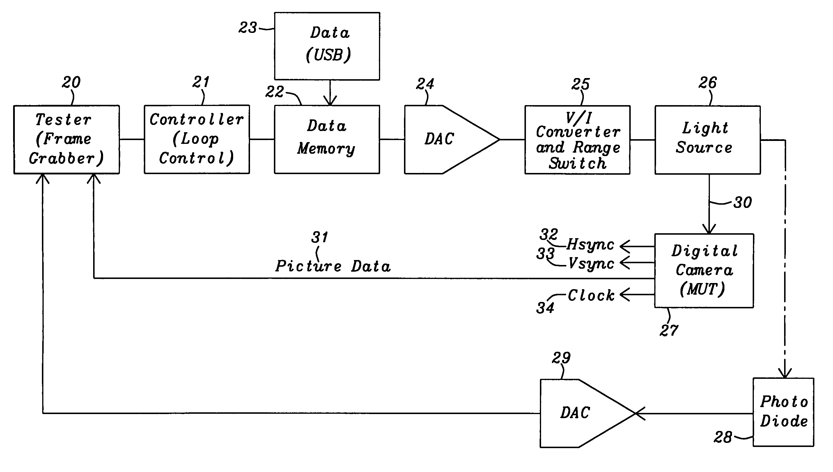
[0032] In FIG. 1 is shown is a block diagram of the present invention showing the control of a light source 26. The light source 26 is contained in a test station used to test a digital camera module (MUT) 27. A tester 20 provides control to a controller 21 and the tester 20 receives back digital picture data from the MUT 27. The controller comprises a FPGA (field programmable gate array), which allows easy reconfiguration of the control of the light source and provides loop control to produce repetitive light waveforms. The controller 21 controls a data memory 22 containing the data (16-bits×1K) necessary to control the output of the DAC 24 coupled to the V / I converter and range switch 25. Data used to control the DAC is loaded into the memory 22 from an USB bus 23.

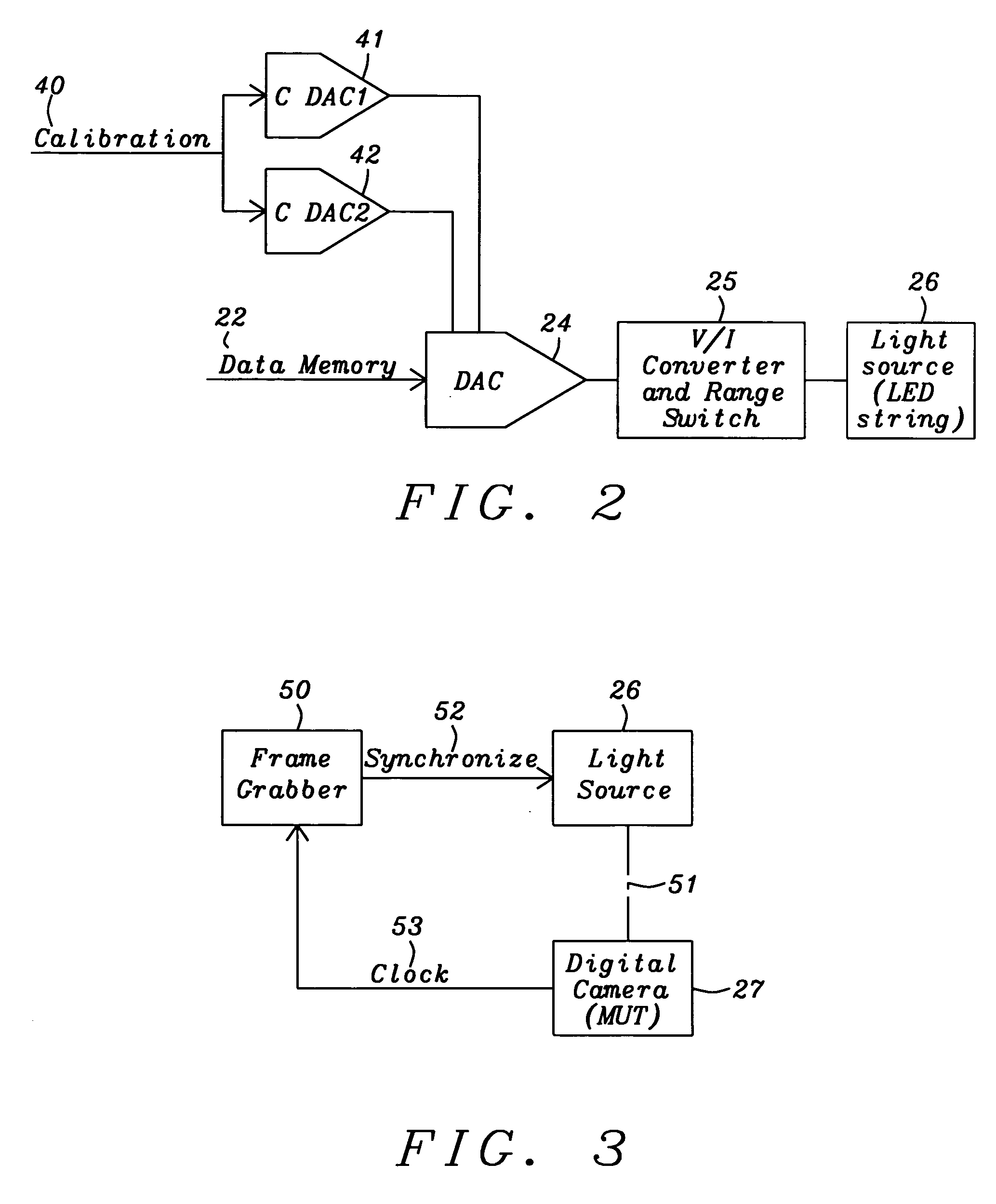
[0033] The DAC is a 12-bit digital to analog converter that controls the V / I converter and range switch 25 to provide a current to turn-on the light source 26. The V / I converter 25 has a current capacity that allows a f...


PUM


Abstract

An intelligent light source for use with the test of a digital camera module provides a plurality of shapes of light. A fast light pulse is created with turn-on and turn-off transitions less than or equal to one microsecond. Other waveform shapes comprise a ramp and a sinusoid, and all shapes can be made to occur once or repetitively. The magnitude of the light has a range from 0.01 LUX to 1000 LUX, and the ramp has a ramp time that has a range from microseconds to 100 ms. The light comprises of a plurality of colors created by serial connected strings of LED devices, where the LED devices in a string emit the same color. The light emanating from the light source is calibrated using a photo diode and the control of a tester by adjusting offset voltages of a DAC controlling a current through the LED strings.

Description

RELATED PATENT APPLICATION [0001] This application is related to U.S. patent application docket number DS04-022, Ser. No. ______, filed on ______, and assigned to the same assignee as the present invention. [0002] This application is related to U.S. patent application docket number DS04-023, Ser. No. ______, filed on ______, and assigned to the same assignee as the present invention. [0003] This application is related to U.S. patent application docket number DS04-025, Ser. No. ______, filed on ______, and assigned to the same assignee as the present invention. [0004] This application is related to U.S. patent application docket number DS04-026, Ser. No. ______, filed on ______, and assigned to the same assignee as the present invention. [0005] This application is related to U.S. patent application docket number DS04-027, Ser. No. ______, filed on ______, and assigned to the same assignee as the present invention.BACKGROUND OF THE INVENTION [0006] 1. Field of Invention [0007] The pre...

Claims


Application Information

Patent Timeline
Patent Type & Authority Applications(United States)
IPC IPC(8): H04N5/222H04N17/00H05B33/00
CPCH04N17/00
Inventor KNOEDGEN, HORSTHUETTMANN, DIRK
Owner RPX CORP
Why Eureka
Try Eureka