
Cooling air intake structure and desk top computer

a technology of cooling air intake and desktop computer, which is applied in the direction of lighting and heating apparatus, electrical apparatus casings/cabinets/drawers, instruments, etc., can solve the problems of more heat generated in the computer and not enough to cool the computer, so as to achieve efficient cooling, enhance the appearance of acceptable design, and improve the effect of cooling efficiency

Inactive Publication Date: 2006-02-23
SONY CORP
View PDF3 Cites 15 Cited by
  • Summary
  • Abstract
  • Description
  • Claims
  • Application Information

AI Technical Summary

Benefits of technology

[0016] It is desirable to provide a cooling air intake structure and a desk-top computer using the air intake structure that achieve aesthetically preferable design, low-noise feature, and efficient cooling.
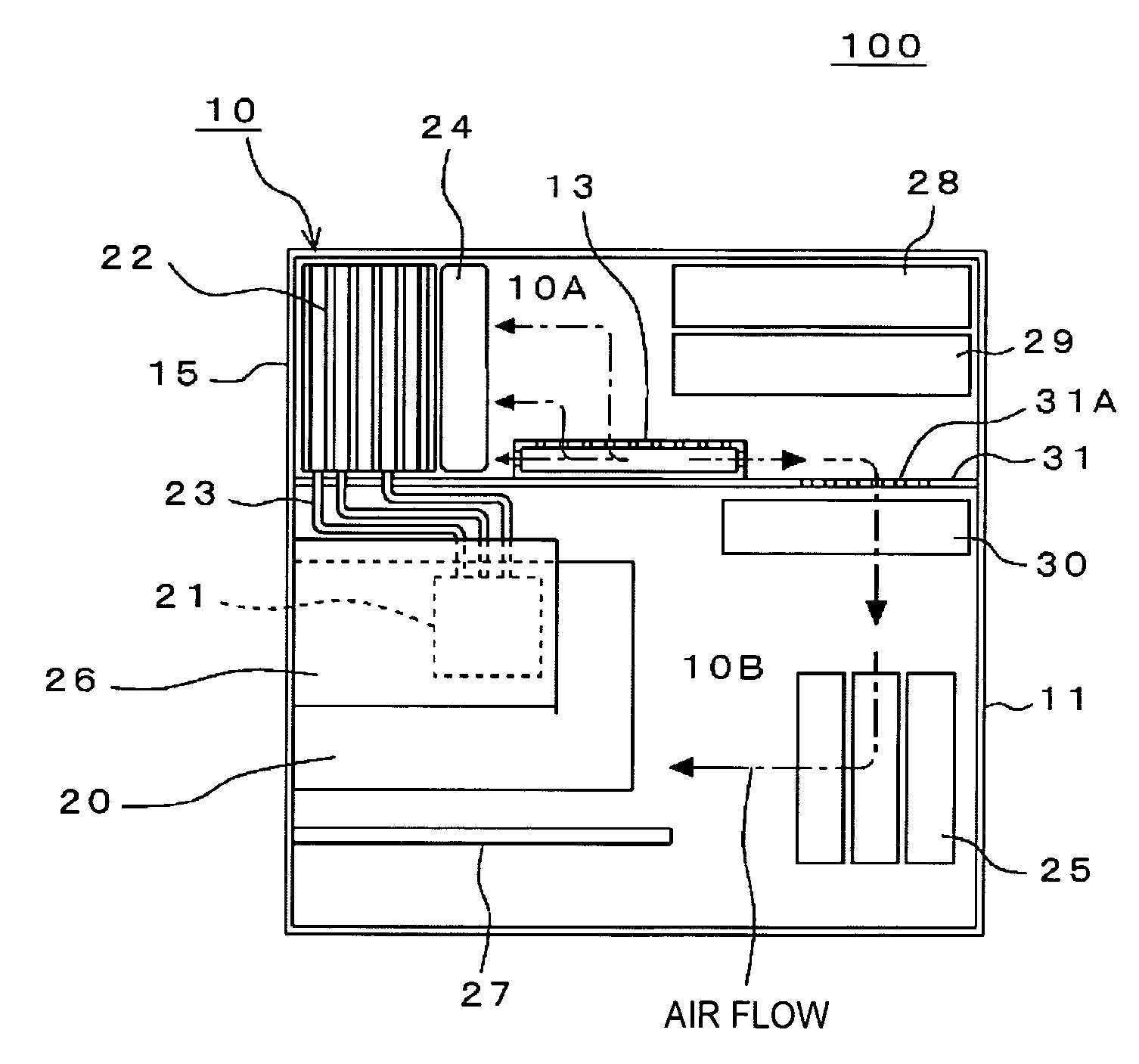
[0019] The cooling air intake structure of the desk-top computer includes one of the passage frame extending from one side to the other side of the housing, defining a passage penetrating through the housing and having a predetermining cross-sectional area, and the recess portion, on each of the sides of the housing, having a predetermined cross-sectional area. With this arrangement, an air intake mechanism is provided without opening the air intake vents on the front panel and the side panel of the computer. The arrangement is aesthetically preferable because the air intake vent is opened in an area hidden in an outside view. The arrangement is free from the sound of wind blowing that could be generated if air is taken in through the air intake vents on the front panel and the side panel. The arrangement controls the leak of the noise of the cooling fan and the sound of an operating hard disk out of the housing. With one of the passage frame and the recess portion arranged close to the component to be cooled, cooling air is directly introduced, and efficient cooling is achieved.
[0025] The air intake structure is provided without the need for the air intake vents on the front panel and the side panel of the housing of the computer. Aesthetically acceptable design is enhanced because the air intake vent is opened in an area not seen from the outside. The arrangement is free from the sound of wind blowing that could be generated if air is taken in through the air intake vents on the front panel and the side panel. The arrangement controls the leak of the noise of the cooling fan and the sound of an operating hard disk out of the housing. With one of the passage frame and the recess portion arranged close to the component to be cooled, cooling air is directly introduced, and efficient cooling is achieved. With the chassis interposed between the processor and the heat sink, heat generated the processor is separated from the internal air of the housing. Even more efficient cooling is performed.
[0026] Since the processor is separated from the heat sink, a large cooling fan is usable, leading to a low-noise level operation.

Problems solved by technology

Heat generated in the computers is more problematic year by year as computer specifications become more sophisticated.
The cooling systems (disclosed in Japanese Unexamined Patent Application Publication No. 2001-42973 and Japanese Unexamined Patent Application Publication No. 2003-306186) are not sufficient to cool the computer.

Method used


Image

  • Cooling air intake structure and desk top computer
  • Cooling air intake structure and desk top computer
  • Cooling air intake structure and desk top computer

Examples


first embodiment

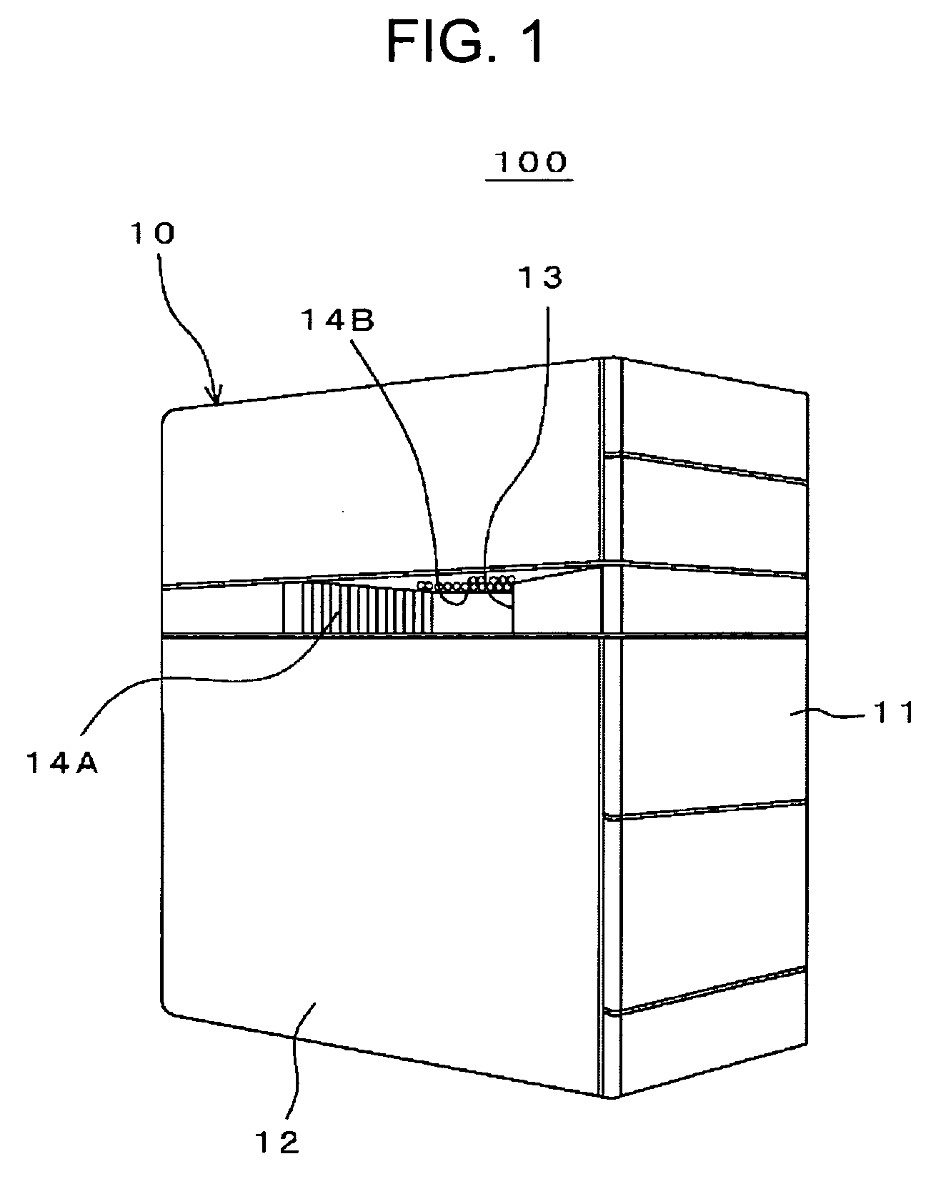
[0038]FIG. 1 is an external view of a computer 100 in accordance with the present invention. The computer 100 has an air intake structure. As shown in FIG. 1, an air intake frame 13 as a passage frame is arranged at a predetermined position of side panels 12 on a housing 10 of the computer 100. The air intake frame 13 has a generally rectangular cross section and includes, in the top portion and the side portions thereof, a plurality of air intake vents 14A and 14B for taking in external air into the housing 10.

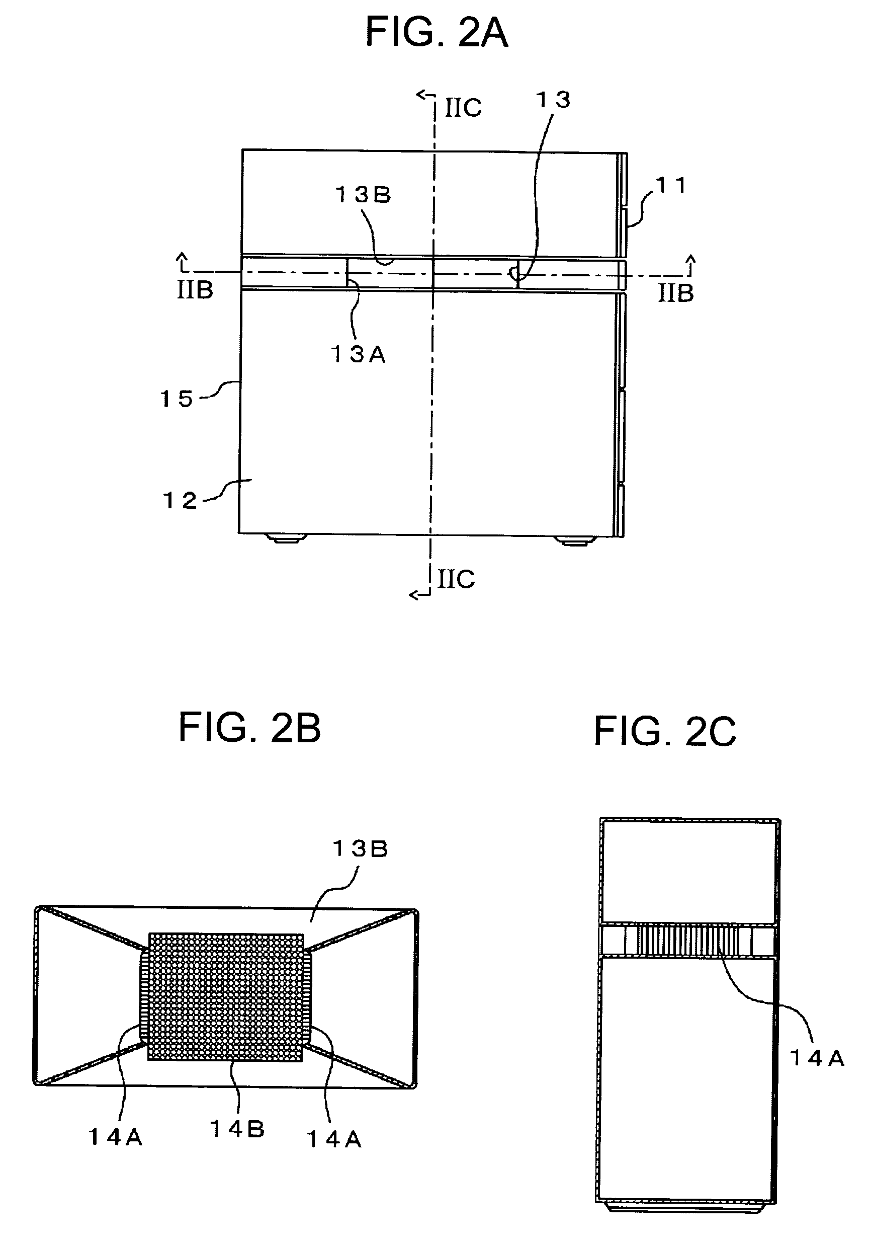
[0039]FIGS. 2A-2C illustrate a layout of the air intake vents of the air intake frame 13. FIG. 2A is a side elevational cross-sectional view of the computer 100. FIG. 2B is a horizontal cross-sectional view of the computer 100 taken along line IIB-IIB in FIG. 2A. FIG. 2C is a vertical cross-sectional view of the computer 100 taken along line IIC-IIC in FIG. 2A.

[0040] As shown in FIG. 2B, the plurality of air intake vents 14B for introducing external air into the housing 10 a...

second embodiment

[0056]FIGS. 6A and 6B illustrate a computer 200 in accordance with the present invention. The computer 200 includes a cooling air intake structure. FIG. 6A is a side view of the computer 200. FIG. 6B is an elevational cross-sectional view of the computer 200, taken along line IVB-IVB in FIG. 6A, with internal components not shown.

[0057] As shown in FIGS. 6A and 6B, the housing 10 of the computer 200 includes an air intake frame 16 as a recess portion on each of both side panels 12. The air intake frame 16 has a round-ended elongated rectangular shape in cross section. The air intake frame 16 includes a side portion 16A and a top portion 16B. A plurality of air intake vents 17A are opened in the side portion 16A, and a plurality of air intake vents 17B are opened in the top portion 16B.

[0058] The computer 200 includes the air intake frame 16, a mother board 20 having a CPU 21, a heat sink 22, a heat pipe 23, a cooling fan 24, a hard disk drive (HDD) 25, a power supply unit 26, a gra...


PUM


Abstract

A cooling air intake structure of a desk-top computer having a housing containing a mother board with a processor, includes one of a passage frame extending from one side to the other side of the housing, defining a passage penetrating through the housing and having a predetermining cross-sectional area, and a recess portion, on each of the sides of the housing, having a predetermined cross-sectional area. The passage frame and the recess portion have a plurality of air intake vents in the wall thereof.

Description

CROSS REFERENCES TO RELATED APPLICATIONS [0001] The present invention contains subject matter related to Japanese Patent Application JP 2004-139137 filed in the Japanese Patent Office on May 7, 2004, the entire contents of which are incorporated herein by reference. BACKGROUND OF THE INVENTION [0002] 1. Field of the Invention [0003] The present invention relates to a cooling air intake structure and a desk-top computer employing the same. [0004] 2. Description of the Related Art [0005] Computer performance, particularly of personal computers, has substantially advanced. The amount of heat generated by a processor (hereinafter central processing unit (CPU)) of a computer increases accordingly. A cooling system for quickly discharging a large amount of heat generated by the CPU out of the computer becomes important. [0006] A heat dissipation pad, a heat sink, a heat pipe, a cooling fan, etc. are used alone or in combination to cool the computer. In high-performance computers, particul...

Claims


Application Information

Patent Timeline
Patent Type & Authority Applications(United States)
IPC IPC(8): H05K7/20G06F1/20G06F1/18
CPCG06F1/20G06F1/181
Inventor KUMANO, DAIGAKUKOBAYSHI, NORIOKANNO, RYUTAKUROSU, SHIGERUNAKAMURA, YOSHIHIROKITARU, KATSUNORIKAINO, MASAZUMIISHIKAWA, MASAYUKI
Owner SONY CORP
Learn More