Motion vector estimating method and motion picture processor

a technology of motion vector and motion picture, which is applied in the field of motion vector estimation method and motion picture processor, can solve the problems of wasteful electric power consumption, and achieve the effect of improving the speed of estimating motion vector and enhancing the effect of digital signal processing

Active Publication Date: 2006-02-23
PANASONIC SEMICON SOLUTIONS CO LTD
View PDF4 Cites 4 Cited by
  • Summary
  • Abstract
  • Description
  • Claims
  • Application Information

AI Technical Summary

Benefits of technology

[0058] According to the above-described structure, an advantage of a digital signal process can be exhibited.
[0059] According to the present invention, since the packing data of the object data and the reference data is sorted in accordance with a sub-sampling method and picture data used for estimating a motion vector is packed again, a parallel calculation for the number of packs can be achieved and a calculation process speed for estimating the motion vector can be greatly improved.

Problems solved by technology

Further, since the unnecessary data is read, electric power is wastefully consumed.

Method used


Image

  • Motion vector estimating method and motion picture processor
  • Motion vector estimating method and motion picture processor
  • Motion vector estimating method and motion picture processor

Examples


first embodiment

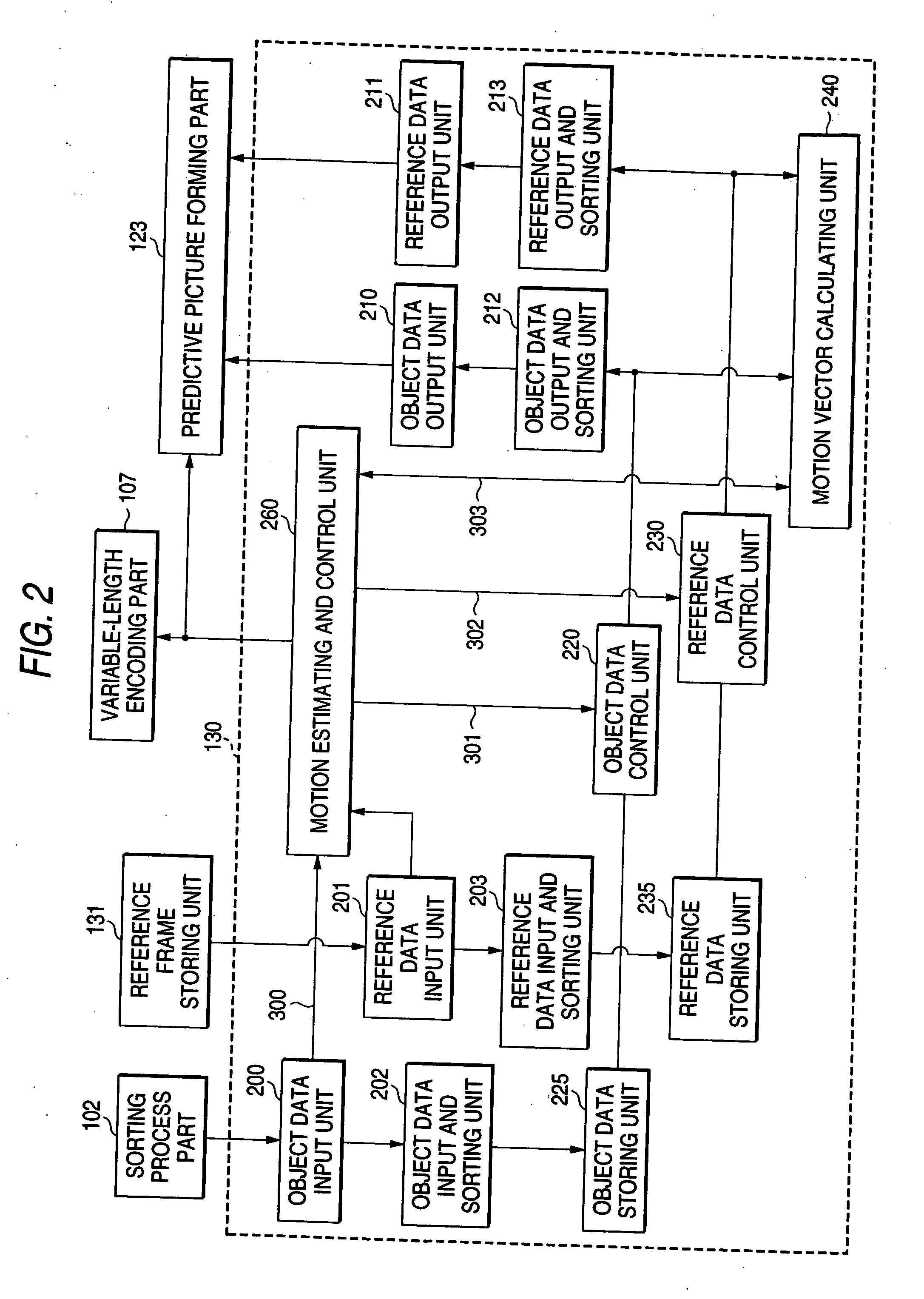
[0115]FIG. 2 is a block diagram showing the structure of a motion vector estimator according to a first embodiment of the present invention and shows a specific structural example of the motion estimating part 130 shown in FIG. 19.

[0116] In FIG. 2, the motion estimating part 130 includes a motion estimating and control unit 260, a motion vector calculating unit 240, an object data control unit 220, an object data input unit 200, an object data input and sorting unit 202, an object data storing unit 225, an object data output and sorting unit 212, an object data output unit 210, a reference data control unit 230, a reference data input unit 201, a reference data input and sorting unit 203, a reference data storing unit 235, a referenced at a output and sorting unit 213 and a reference data output unit 211.

[0117] The motion estimating and control unit 260 controls the entire part of the motion estimating part 130. The object data control unit 220 performs a control for reading objec...

second embodiment

[0154] A pixel sub-sampling method effective for estimating the motion vector at high speed is not limited to the pixel sub-sampling method having a checkered pattern shown in FIG. 18. For instance, pixel sub-sampling methods shown in FIGS. 21 to 23 are also effective for calculating an evaluation function at high speed. In this case, the packing data of four data needs to be sorted as shown in FIGS. 24 to 26 respectively in place of the sorting method shown in FIG. 13.

[0155] In the second embodiment, sorting processes to various arrangements according to the pixel sub-sampling method can be realized. FIG. 8 is a block diagram showing the structure of a motion vector estimator according to the second embodiment of the present invention and a specific structural example of the motion estimating part 130 shown in FIG. 19 in this embodiment.

[0156] In FIG. 8, a motion estimating part 130c includes a motion estimating and control unit 260c, a sampling factor 261, a motion vector calcul...

third embodiment

[0177]FIG. 10 is a block diagram showing the structure of a motion vector estimator according to a third embodiment of the present invention and a specific structural example of the motion estimating part 130 shown in FIG. 19. In this embodiment, a second object data storing unit and a second reference data storing unit for storing picture data of an arrangement A are provided as well as an object data storing unit and a reference data storing unit for storing picture data whose arrangement is changed to an arrangement B to estimate a motion vector. Thus, the picture data of the arrangement A can be outputted without performing a sorting process after the motion vector is estimated.

[0178] In FIG. 10, a motion estimating part 130d includes a motion estimating and control unit 260d, a motion vector calculating unit 240, an object data control unit 220d, an object data input unit 200, an object data input and sorting unit 202, an object data storing unit 225, a second object data stor...


PUM


Abstract

A motion vector estimator includes an object data input and sorting unit and a reference data input and sorting unit for sorting packed input picture data to separate first picture data used for estimating the motion vector from second picture data that is not used for estimating the motion vector and pack the picture data again respectively, an object data storing unit and a reference data storing unit for storing the repacked first picture data and the second picture data, and a motion vector calculating unit for reading the first picture data from the object data storing unit and the reference data storing unit to perform a calculation for estimating the motion vector.

Description

[0001] This application is based on Japanese Patent Applications No. 2004-239134 and 2005-172736, which are incorporated herein by reference. BACKGROUND OF THE INVENTION [0002] 1. Field of the Invention [0003] The present invention relates to a motion vector estimating technique for compensation and predictive encoding of a movement in a motion picture compressing and encoding process. More particularly, the present invention relates to a motion vector estimating method and a motion picture processor that applies a sub-sampling method to the input picture data of a picture of an object frame and a picture of a reference frame. [0004] 2. Description of the Related Art [0005] In recent years, a motion picture compressing and encoding technique such as an MPEG for performing a highly efficient encoding process has been rapidly progressively put to practical use and spread in video cameras or mobile phones or the like. In the motion picture compressing and encoding technique such as the...

Claims


Application Information

Patent Timeline
Patent Type & Authority Applications(United States)
IPC IPC(8): H04N11/02H04N7/12H04B1/66H04N11/04G06T7/20H04N5/225H04N19/423H04N19/436H04N19/46H04N19/463H04N19/50H04N19/503H04N19/51H04N19/517H04N19/577H04N19/59H04N19/61H04N19/625H04N19/70H04N19/85H04N19/91
CPCH04N19/61H04N19/59H04N19/433
Inventor TANAKA, YASUHARUKITAMURA, SHINJI
Owner PANASONIC SEMICON SOLUTIONS CO LTD
Why Eureka
Try Eureka