Machine for the formation of metal mesh and relative method

a technology of metal mesh and machine, applied in the field of metal mesh machine, can solve the problems of long downtime, inability to reach satisfactory productivity levels, low productivity, etc., and achieve the effect of reducing downtime, speeding up the time required for wire inserting, and improving productivity

Inactive Publication Date: 2005-11-10
BETA SYSTEMS
View PDF3 Cites 5 Cited by
  • Summary
  • Abstract
  • Description
  • Claims
  • Application Information

AI Technical Summary

Benefits of technology

[0023] The use of thrust means therefore allows to limit the travel of the prehensile member and to speed up the times required to insert the wires, thus reducing the downtimes of the machine due to the positioning of the transverse wires, with a considerable advantage in terms of productivity.

Problems solved by technology

One of the main limits of such machines is their low productivity, caused by the need to feed the transverse wires at a certain distance from the welding assembly, and then move them to the attachment position by means of the positioning means.
This entails long downtimes due to the traveling time of the transverse wires in the feed step, since the front end of the wires has to pass through the whole width of the machine, and also due to the subsequent movement of the transverse wires to the attachment position.
While such solutions have allowed a partial reduction in downtimes, they have not allowed to reach satisfactory levels of productivity, since the times needed for the positioning means to travel from the attachment position to the preparation position and vice versa are still too long.

Method used


Image

  • Machine for the formation of metal mesh and relative method
  • Machine for the formation of metal mesh and relative method
  • Machine for the formation of metal mesh and relative method

Examples


Embodiment Construction

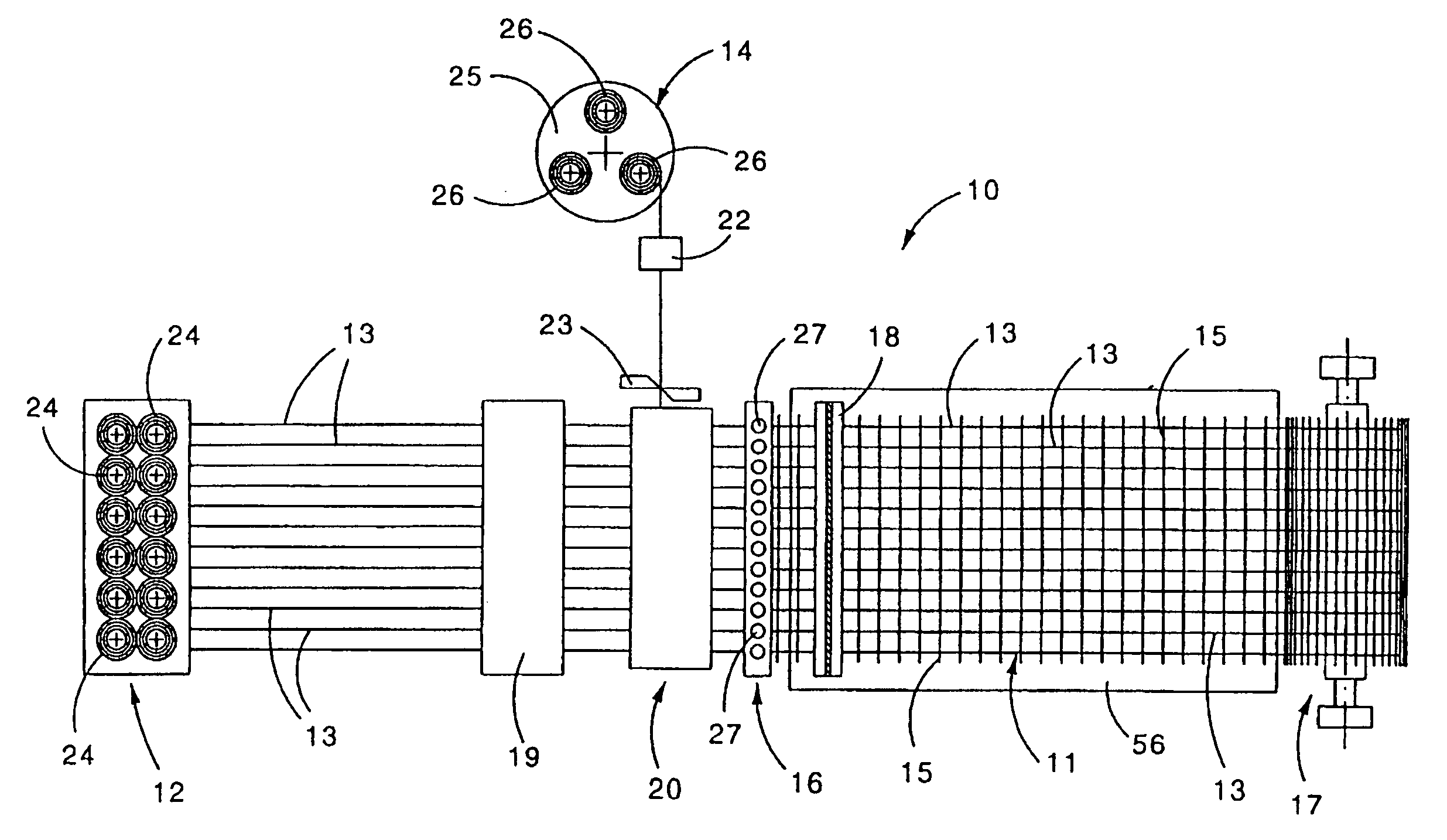
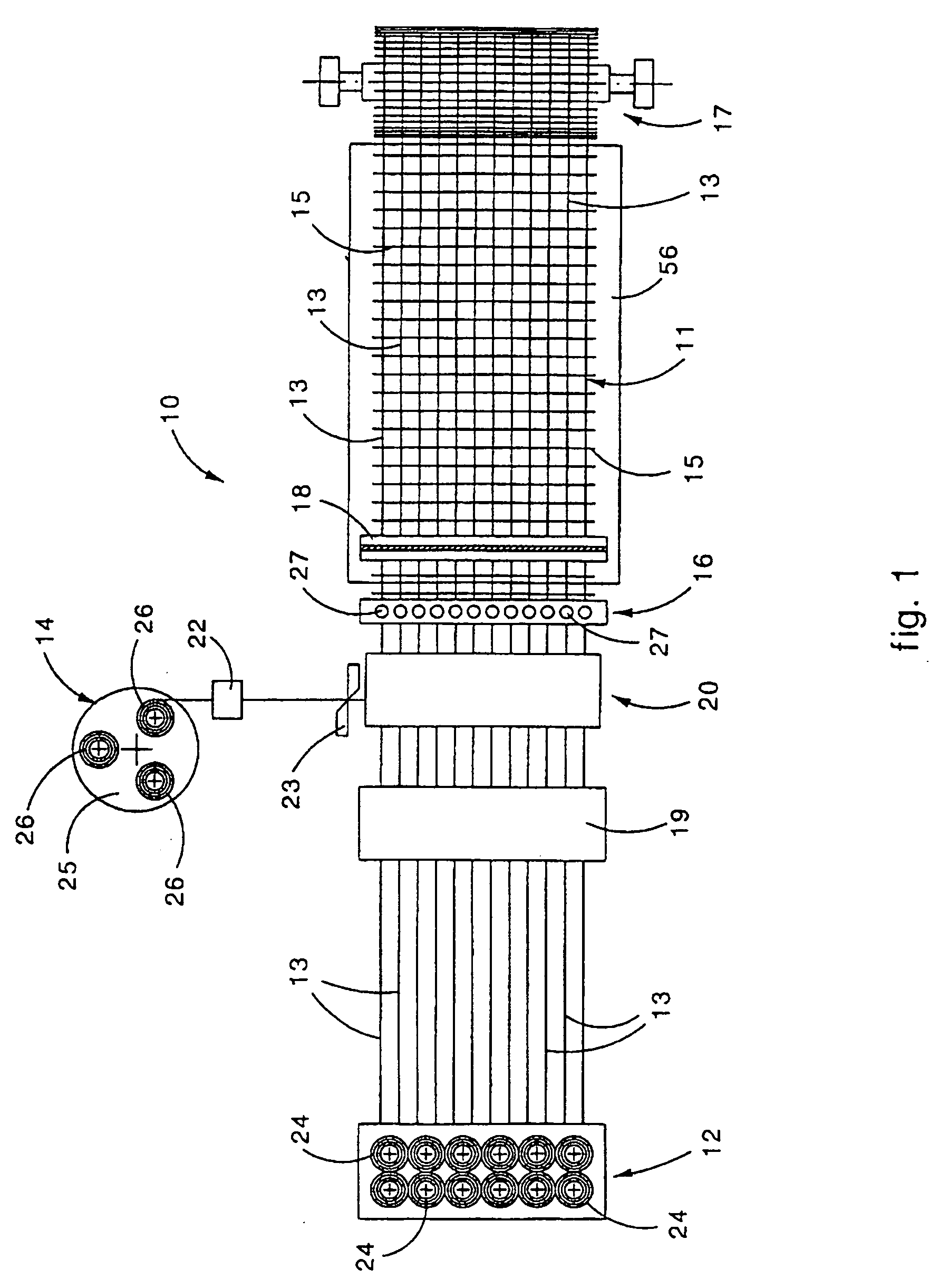
[0032] With reference to the attached figures, the number 10 denotes generally a machine for the formation of metal wire mesh 11 according to the present invention.

[0033] The machine 10 substantially comprises: a feed and advance assembly 12 for the longitudinal wires 13, a feed assembly 14 and a positioning apparatus 20 for transverse wires 15, a welding assembly 16, a shears 18 to shear the mesh 11 into sheets and a winding drum 17 onto which the mesh 11 can be wound in a coil (FIG. 1).

[0034] The drum 17 and the shears 18 can be present and / or operating alternately with each other.

[0035] The feed and advance assembly 12 comprises a plurality of reels 24 from which the longitudinal wires 13 are unwound; in this case, the longitudinal wires 13 are subjected to straightening by a first straightening device 19 and then made to advance towards the welding assembly 16 through respective guide conduits 21 (FIG. 6).

[0036] The feed assembly 14 in this case comprises a carousel 25 on wh...


PUM

PropertyMeasurementUnit
thrustaaaaaaaaaa
relative movementaaaaaaaaaa
movementaaaaaaaaaa

Abstract

Machine for the formation of a metal mesh obtained by attaching together a plurality of longitudinal metal wires to a plurality of transverse metal wires. The machine includes a first feed assembly to make the longitudinal wires advance step-wise, a second feed assembly to arrange one transverse wire at a time in a first preparation position, a positioning apparatus to arrange the transverse wire in a second attachment position, and a welding assembly to attach the transverse wires to the longitudinal wires. The positioning apparatus includes a loading assembly, provided with a gripping and transfer device, to locate the transverse wire in the second attachment position. The machine also includes a thrusting device to take the transverse wire from the first preparation position to a third intermediate pick-up position, near the second attachment position, wherein the transverse wire is picked up by the gripping and transfer device. The thrusting device includes a rotary element provided with blade able to thrust the transverse wire from the first preparation position to the third intermediate pick-up position.

Description

FIELD OF THE INVENTION [0001] The present invention concerns a machine used for the production of a metal mesh and the relative production method. [0002] The invention is applied preferentially, but not exclusively, to make electro-welded mesh used as metal reinforcement elements for structures made of reinforced concrete. [0003] For this reason, in the following description we shall make specific reference to this application, although the invention can also be used for the formation of other types of mesh. BACKGROUND OF THE INVENTION [0004] Various machines are known for the production of electro-welded mesh, each one consisting of a plurality of longitudinal metal wires or round pieces, distanced from each other, on which corresponding transverse metal wires or round pieces are welded perpendicularly and according to a pre-determined interaxis. [0005] Such machines generally comprise at least an assembly to feed and advance the longitudinal wires, an assembly to feed the transver...

Claims


Application Information

Patent Timeline
Patent Type & Authority Applications(United States)
IPC IPC(8): B21F23/00B21F27/10B21F27/20
CPCB21F23/005B21F27/20B21F27/10
Inventor TABOGA, ERMANNO
Owner BETA SYSTEMS
Why Eureka
Try Eureka