
Apparatus and method for beamforming in a multi-antenna system

Active Publication Date: 2006-02-23
SAMSUNG ELECTRONICS CO LTD +1
View PDF4 Cites 34 Cited by
  • Summary
  • Abstract
  • Description
  • Claims
  • Application Information

AI Technical Summary

Benefits of technology

[0018] Furthermore, the present invention provides a beamforming apparatus and method for minimizing the amount of feedback information, while guaranteeing a maximum amount for transmission data, in a multi-antenna system.

Problems solved by technology

Multipath interference, shadowing, propagation attenuation, time-varying noise, and interference in a wireless channel environment are factors deteriorating the high-speed, high-quality data service.
The increase in the amount of the feedback information increases the amount of radio resources used for transmitting the feedback information, causing an increase in radio traffic.
In addition, the increase in the amount of the feedback information increases the number of calculations for beamforming, and the increase in the number of the calculations increases a load on the system.

Method used


Image

  • Apparatus and method for beamforming in a multi-antenna system
  • Apparatus and method for beamforming in a multi-antenna system
  • Apparatus and method for beamforming in a multi-antenna system

Examples


first embodiment

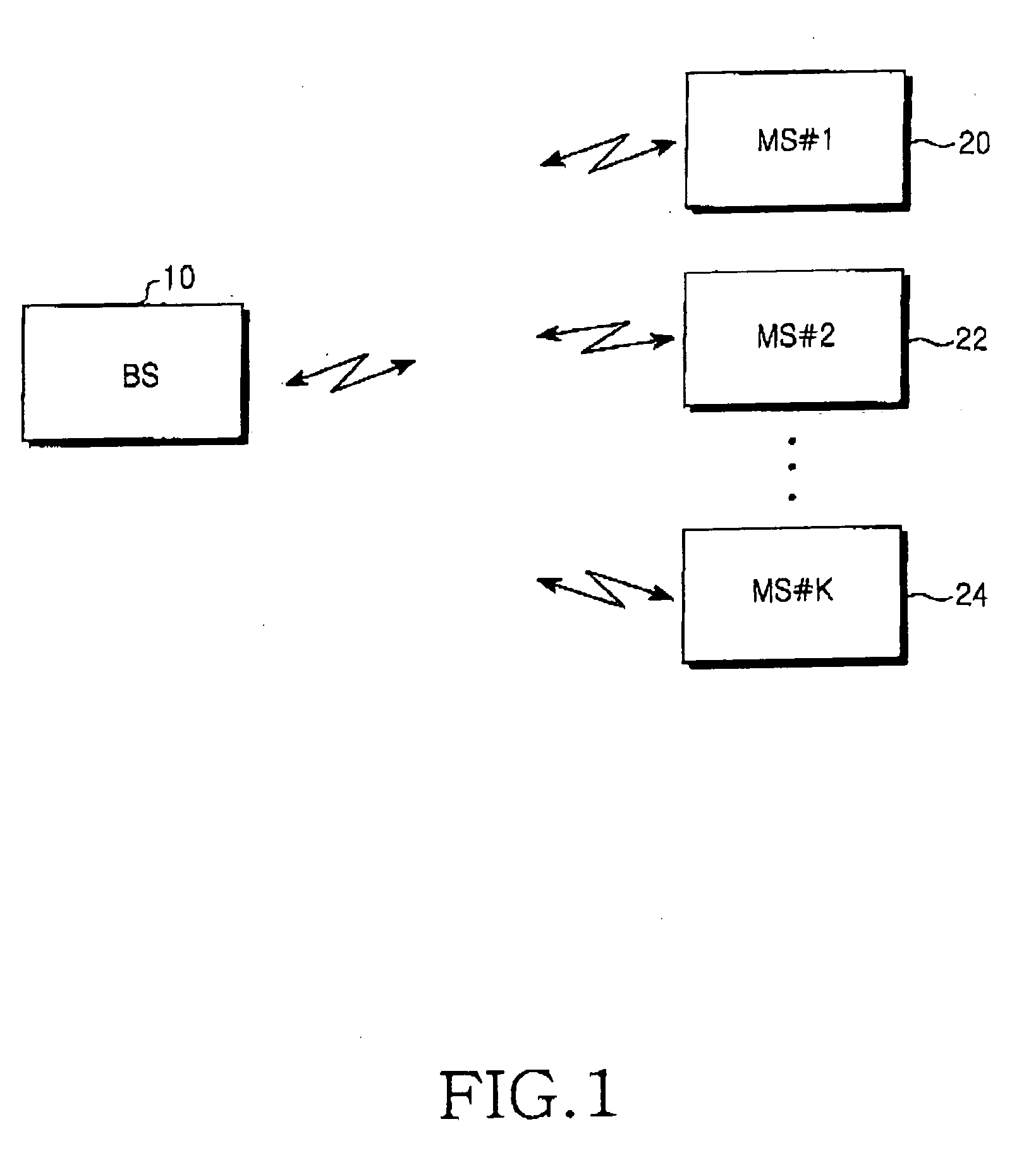
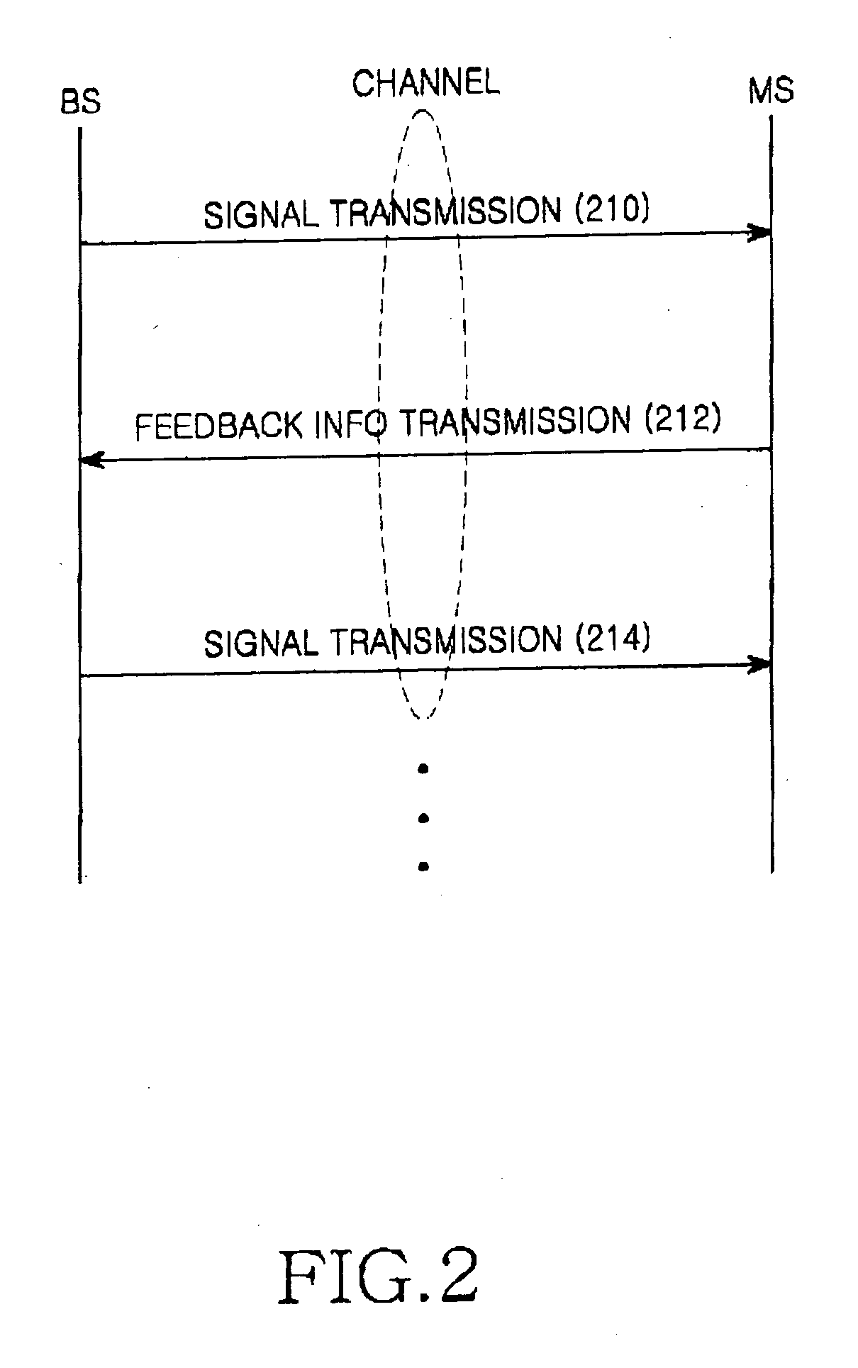
[0062] A detailed description will now be made of a method for generating feedback information and transmitting the generated feedback information in a reception side (i.e. mobile station) according to the present invention.

[0063] A received signal y(t) is defined by Equation 1. y⁢ ⁢(t)=EsNt⁢H⁢ ⁢(t)⁢ ⁢x⁢ ⁢(t)+n⁢ ⁢(t)=EsNt⁢H⁢ ⁢(t)⁢ ⁢W⁢ ⁢(t)⁢ ⁢s⁡(t)+n⁢ ⁢(t)(1)

where H(t) denotes an Mr×Mt MIMO channel matrix transmitted from a base station (or Node B), s(t) denotes an Mt×1 transmitted symbol vector, n(t) denotes an Mr×1 additive white Gaussian noise (AWGN) vector with distribution CN(0,N0 / 2IMr) for each element, W(t) denotes a matrix used for beamforming transmission, x(t) denotes a signal vector transmitted by a beamformer (x(t)=W(t)s(t))), and y(t) denotes an Mr×1 received symbol vector (t: an index of a timeslot).

[0064] Using the received signal y(t), the mobile station finds a weight matrix provided for obtaining of the maximum throughput or the maximum amount of transmission dat...

second embodiment

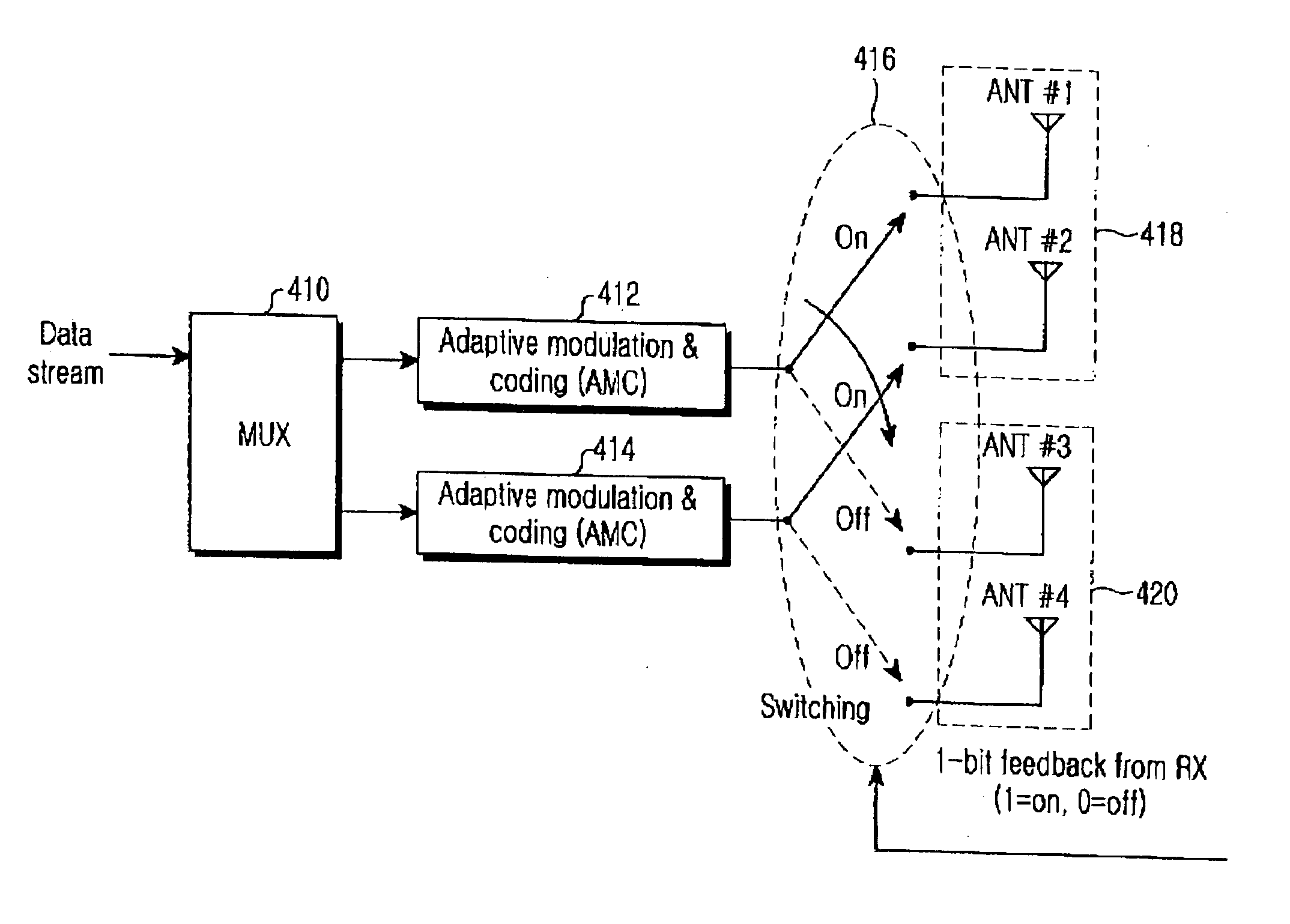
[0079] As described above, the present invention allocates different weights W1 and W2 to the transmission antenna groups, which are determined by the feedback information processor 304 (FIG. 3) depending on the feedback information from the mobile station. The feedback information processor 304 (FIG. 3), together with the mobile station, predefines the weights available in the base station, in order to determine the weights. The feedback information processor 304 (FIG. 3) selects weights corresponding to weight index information provided from the mobile station, and delivers the selected weights to the first and second combiners 516 and 518.

[0080] In the base station, the feedback information processor 304 (FIG. 3) can be implemented such that it can calculate different weights to be allocated to the transmission antenna groups depending on the weight index information k. An example of a weight matrix pattern predefined between a base station and a mobile station to allocate differ...

third embodiment

[0089] The weights W11, W21, W12, and W22 in the combiner 616 are determined by the feedback information processor 304 (FIG. 3) depending on the feedback information from the mobile station. The feedback information processor 304 (FIG. 3), together with the mobile station, predefines a weight matrix to be used in the base station, in order to determine the weights W11, W21, W12, and W22. The feedback information processor 304 (FIG. 3) calculates the weights W11, W21, W12, and W22 depending on the feedback information provided from the mobile station. The feedback information processor 304 (FIG. 3) controls an operation of the combiner 616 depending on the weight matrix in which the calculated weights W11, W21, W12, and W22 are reflected. The weight index information is comprised of k1 and k2, each of which is expressed with 2 bits. Therefore, in the present invention, 4-bit weight index information is used as feedback information.

[0090]FIG. 7 graphs performance of each of the first ...


PUM


Abstract

An apparatus and method for performing beamforming for transmitting a plurality of bit streams output through Adaptive Modulation and Coding (AMC) via a plurality of transmission antennas in a base station using a multi-antenna scheme. The apparatus and method include classifying the plurality of transmission antennas into a plurality of transmission antenna groups; selecting one of the transmission antenna groups depending on a group selection signal being fed back from a mobile station; and outputting each of the bit streams to its associated transmission antenna among the transmission antennas constituting the selected transmission antenna group.

Description

PRIORITY [0001] This application claims priority under 35 U.S.C. § 119 to an application entitled “Apparatus and Method for Beamforming in a Multi-Antenna System” filed in the Korean Intellectual Property Office on Jul. 13, 2004 and assigned Serial No. 2004-54565, the contents of which are incorporated herein by reference. BACKGROUND OF THE INVENTION [0002] 1. Field of the Invention [0003] The present invention relates generally to an apparatus and method for beamforming in a multi-antenna system, and in particular, to an apparatus and method for performing beamforming depending on feedback information. [0004] 2. Description of the Related Art [0005] Mobile communication systems are evolving into high-speed, high-quality wireless packet data communication systems capable of providing data service and multimedia service beyond the early voice-oriented service. The ongoing standardization on High Speed Downlink Packet Access (HSDPA) being led by 3rd Generation Partnership Project (3GP...

Claims


Application Information

Patent Timeline
IPC IPC(8): H04L1/02
CPCH04B7/061H04B7/0617H04W52/262H04L1/0003H04L1/0009H04B7/0691H04B7/0417
Inventor KIM, HO-JINLEE, JU-HOLEE, KWANG-BOKPARK, HYOUNG-WOONYANG, HOASHISH, PANDHARIPANDEKIM, SUNG-JIN
Owner SAMSUNG ELECTRONICS CO LTD
Learn More