Fluid dynamic bearing motor attached at both shaft ends

a technology motors, applied in the direction of sliding contact bearings, mechanical energy handling, mechanical equipment, etc., can solve the problems of increased risk of lubricant leakage out of fluid dynamic bearings, imbalances and shocks, and difficult realization of fluid dynamic bearing designs for motors attached at both ends, and achieve high precision

Inactive Publication Date: 2006-02-23
KURA LAB
View PDF9 Cites 40 Cited by
  • Summary
  • Abstract
  • Description
  • Claims
  • Application Information

AI Technical Summary

Benefits of technology

[0017] Thus, it is an object of the present invention to provide a fixed shaft type fluid dynamic bearing structure suitable for use in low profile motor for driving a few magnetic disk or the like at high precision.

Problems solved by technology

However, such fluid dynamic bearing is suffering from a number of disadvantages, for example, it could be sensitive to external vibration, imbalances and shock.
All of the known fluid dynamic bearing designs for a motor attached at both ends has not been easy to realize.
Opening a motor at both ends greatly increases the risk of lubricant leakage out of the fluid dynamic bearing.
This leakage is caused by, among other things, small differences in net flow rate created by differing pumping pressures in the bearing.
Moreover, due to manufacturing imperfections of the bearing, the gap in the bearing may not be uniform along its length and this can create pressure imbalance in the bearing and hence, cause leakage when both ends of the fluid dynamic bearing are open.
Thus, it is difficult to employ the structure of these motors for low profile drives which carry and drive no more than two small magnetic disks or the like.
Thus, if such structure is simply miniaturized for use in a small sized motor, the same arrangement cannot secure the span between the upper and lower radial bearings, failing to maintain low non-repetitive runout during rotation.
Above all, the greater number of parts makes cost reduction difficult.
That is suitable for low profile HDDs, however it cannot support heavy load, multiple disks.
Both proposals have two thrust bearings at the both ends of radial bearing, however their bearing structure have the possibility of lubricant leakage because of dimensional inperfections of the bearing part or the bearing gap gradient whcih may occur in mass production stage.
And also its radial span should be short because of many parts along the shaft, then it cannot achieve low non-repetitive runout.
The later proposal has the defect that the bearing loss becomes large because of large radial bearing radius.

Method used


Image

  • Fluid dynamic bearing motor attached at both shaft ends
  • Fluid dynamic bearing motor attached at both shaft ends
  • Fluid dynamic bearing motor attached at both shaft ends

Examples


first embodiment

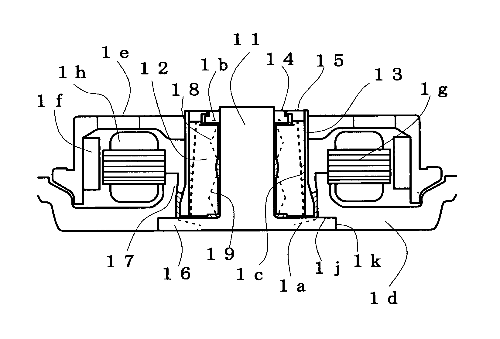
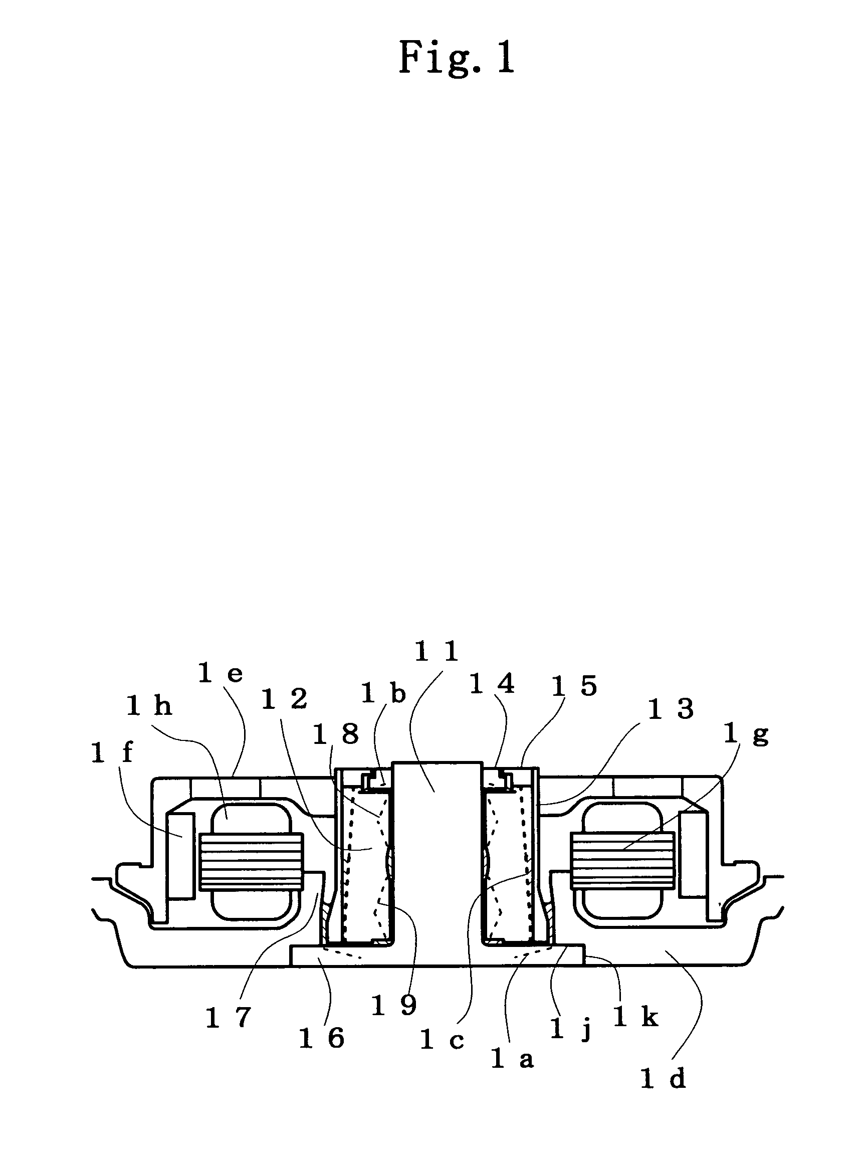
[0058]FIG. 1 is a vertical sectional view of a fixed shaft type fluid dynamic bearing motor which is the present invention.

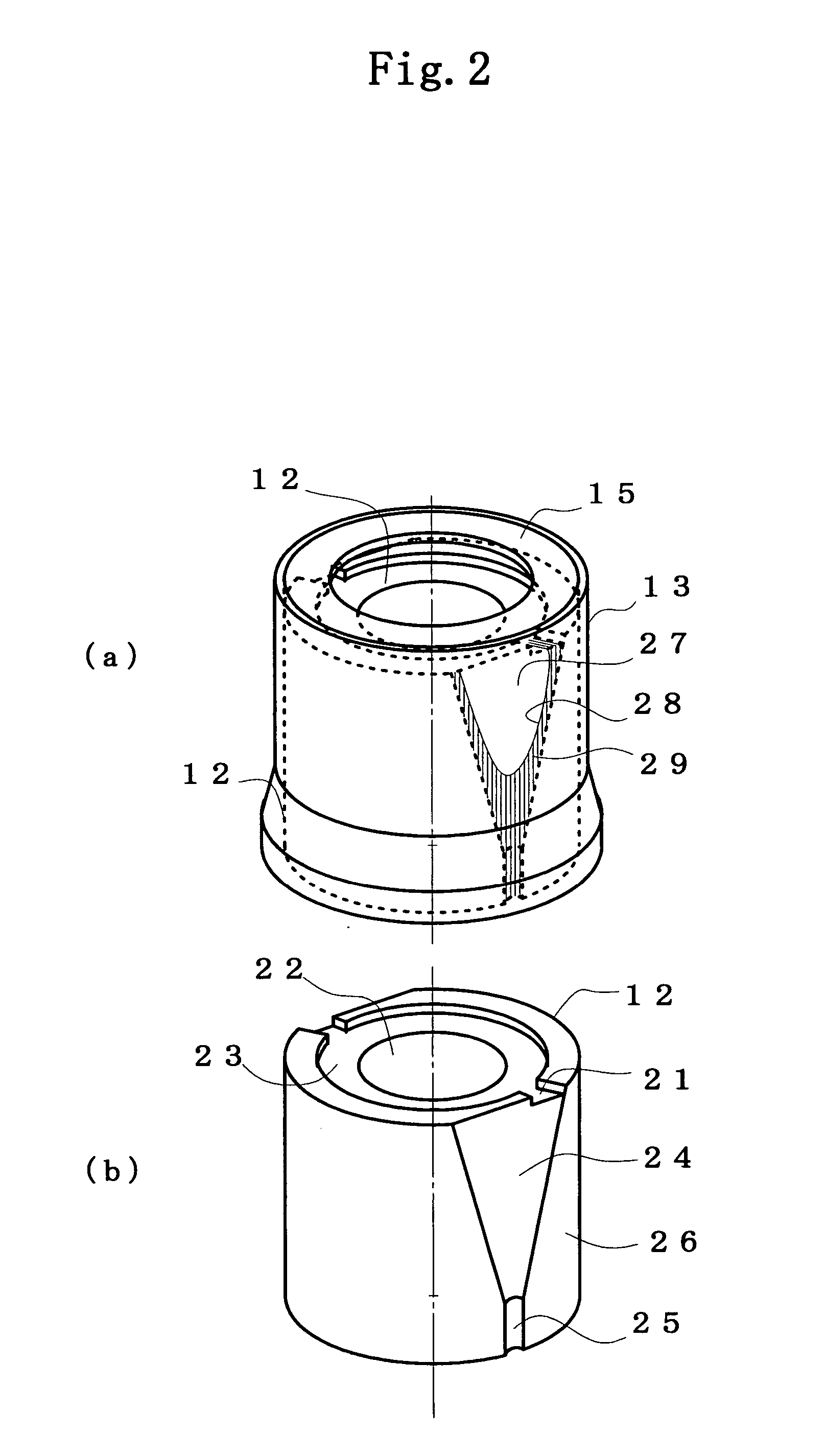
[0059] A fixed shaft 11 is a T-shaped cylindrical shaft which is composed of a cylindrical shaft and a flange 16. The sleeve, which rotatably fits to a T-shaped cylindrical shaft 11, is composed of an inner cylinder 12 and an outer cylinder 13. The upper and lower end surfaces of the inner cylinder 12 are opposing the first annular member 14 which is fixed to the shaft 11 and the flange 16 with small gap respectively.

[0060] The second annular member specified in claim 1 corresponds to the flange 16 and the part 17 of the base plate 1d (hereinafter, referred to as an annular member 17). The numeral 1c represents channels formed in the sleeve and having an intake portion near the outer region of the first annular member 14 and an outlet portion near the periphery of the bottom end of the sleeve. A lubricant is continuously filled into the gap between the shaft 11...


PUM


Abstract

A fixed shaft type fluid dynamic bearing motor having two interfaces of a lubricant at least, in which a channel leading from near the outer region of a rotating sleeve top end to near the periphery of the bottom of the sleeve is formed in the sleeve. The lubricant near the outer region of a rotating sleeve top end is thrown out into the channel by centrifugal force, and further conveyed to near the periphery of the bottom of the sleeve by centrifugal force and/or by slanted channel in circumferential direction. A dynamic-pressure generating groove for pumping the lubricant toward the top end of the sleeve is formed between the fixed shaft and the sleeve. The dynamic-pressure generating groove and the centrifugal force cause the circulation of the lubricant, thereby sealing the lubricant. According to the invention, axial space smaller than that of tapered seals can be utilized to achieve a low-profile recording disk drive.

Description

[0001] This is a continuation-in-part application of Ser. No. 11 / 109,691 filed on Apr. 20, 2005. The entire content of the application is hereby incorporated by reference.BACKGROUND OF THE INVENTION [0002] 1. Field of the Invention [0003] The invention relates to a fluid dynamic bearing motor for a recording disk drive, and more particularly to a fluid dynamic bearing motor attached at both shaft ends (a fixed shaft type fluid dynamic bearing motor) which uses a novel lubricant sealing structure as an alternative to conventional tapered seals. [0004] 2. Description of the Related Art [0005] The dominant bearing structure in conventional fluid dynamic bearing motors for magnetic disk drives (HDDs) has been a rotating shaft structure in which a lubricant and air form only a single interface to facilitate sealing in the lubricant. However, such fluid dynamic bearing is suffering from a number of disadvantages, for example, it could be sensitive to external vibration, imbalances and sho...

Claims


Application Information

Patent Timeline
Patent Type & Authority Applications(United States)
IPC IPC(8): F16C32/06
CPCF16C17/102H02K7/086F16C33/107F16C17/107F16C33/743F16C17/105F16C2370/12
Inventor ICHIYAMA, YOSHIKAZU
Owner KURA LAB
Why Eureka
Try Eureka