Optical fiber

Active Publication Date: 2006-02-23
THE FUJIKURA CABLE WORKS LTD
View PDF2 Cites 81 Cited by
  • Summary
  • Abstract
  • Description
  • Claims
  • Application Information

AI Technical Summary

Benefits of technology

[0003] Conventionally, transmission systems using WDM (wavelength division multiplexing) and optical fibers therefore have actively been developed in order to increase the transmission capacity of trunk lines or long-distance lines. Optical fibers for WDM transmission are required to have certain characteristics, such as reducing nonlinear effects and suppressing the dispersion. In recent years, optical fibers that exhibit a reduced dispersion slope for a system called “metro” in a span of several hundred kilometers and optical fibers that are almost free from loss due to OH have been proposed.
[0004] When installment of optical fibers into offices and homes (FTTH; Fiber to the Home) is taken into consideration, characteristics different from those of optical fibers used in transmission are required. That is, when installing optical fibers into buildings or houses, a very small amount of bending of a bending diameter of 30 mm φ or 20 mm φ may be generated. In addition, it is crucial that loss is not increased when a fiber is wound with a small bending diameter to accommodate an excess length. In other words, resistance to a small bending is a crucial characteristic for optical fibers for the FTTH. In addition, good connectivity with optical fibers laid between a base station and buildings or h

Problems solved by technology

Furthermore, low cost is required for such an application.
Although there have been reports about optical fibers with smaller bending diameters, such optical fibers have problems, such as having increased splice loss compared with conve

Method used


Image

  • Optical fiber
  • Optical fiber
  • Optical fiber

Examples


example 1

[0093] The refractive index profile of the optical fiber in this example is shown in FIG. 4.

[0094] The optical fiber of this example was manufactured by forming the region labeled as (a) in the figure using the VAD method. Then, after the thus obtained core material using the VAD method was drawn, it was subjected to an outside deposition to form the region (b). After the resulting preform was further drawn, it was subjected to an outside deposition to form the region (c). Upon the formation of the region (b), SiF4 gas was introduced during the process of vitrification, thereby obtaining a refractive index lower than that of silica by addition of F. FIG. 4 is the result of the measurement of the refractive index profiles of the preform obtained by the above-described process using a preform analyzer (brand name: MODEL 2600, manufactured by Kinetics Inc. / York Technology Ltd.). As can be seen from this figure, although the refractive index profile of the optical fiber of this example...

example 2

[0108] The refractive index profile of the optical fiber in this example is shown in FIG. 5. The optical fiber of this example was manufactured following the same procedure as that of the above-described Example 1. FIG. 5 shows the result of the refractive index profile of the preform measured using the preform analyzer. As can be seen from this figure, although the refractive index profile of the optical fiber of this example does not have a perfect step-shaped shape, it can achieve advantageous effects of the present invention.

[0109] Each parameter of the optical fiber of this example was as follows:

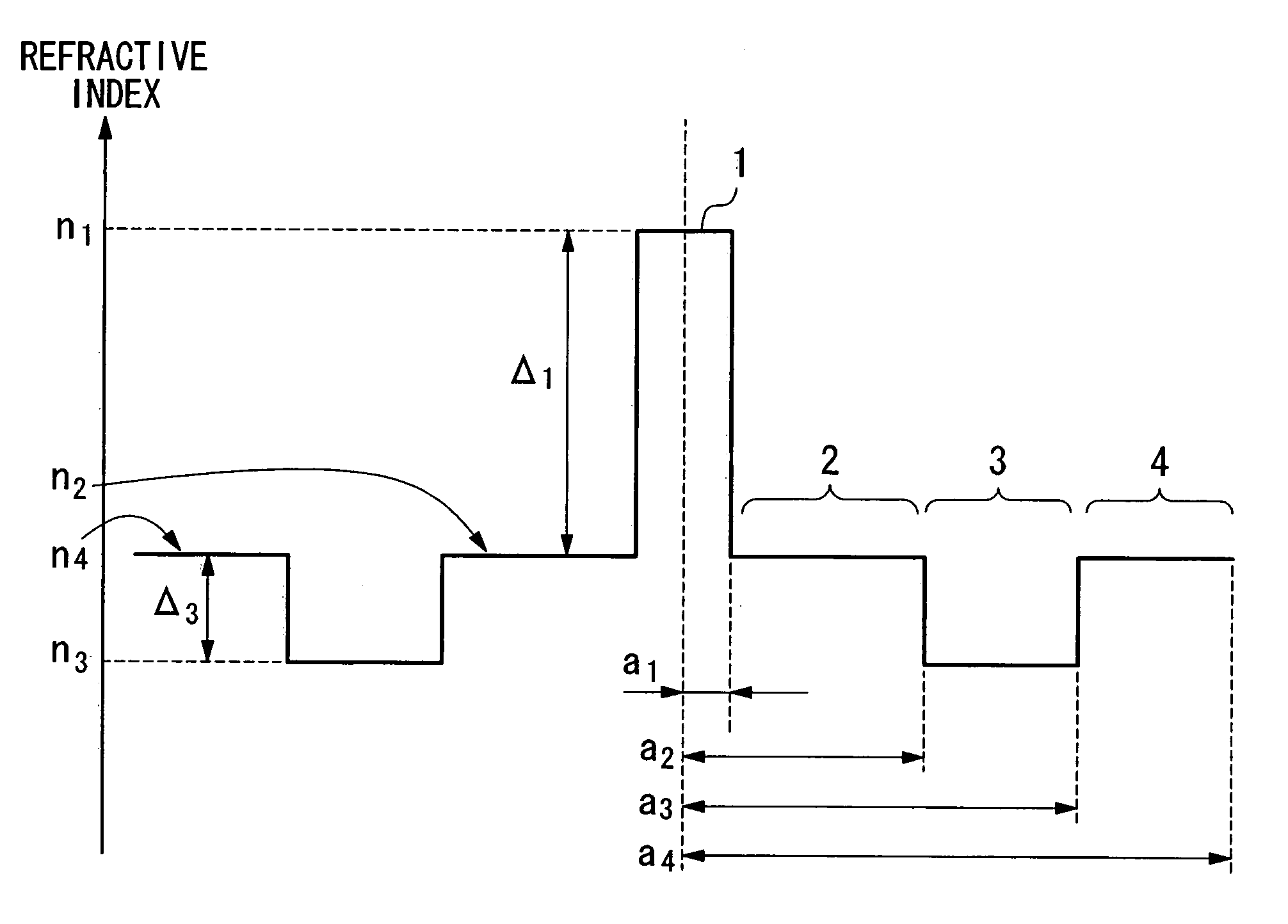
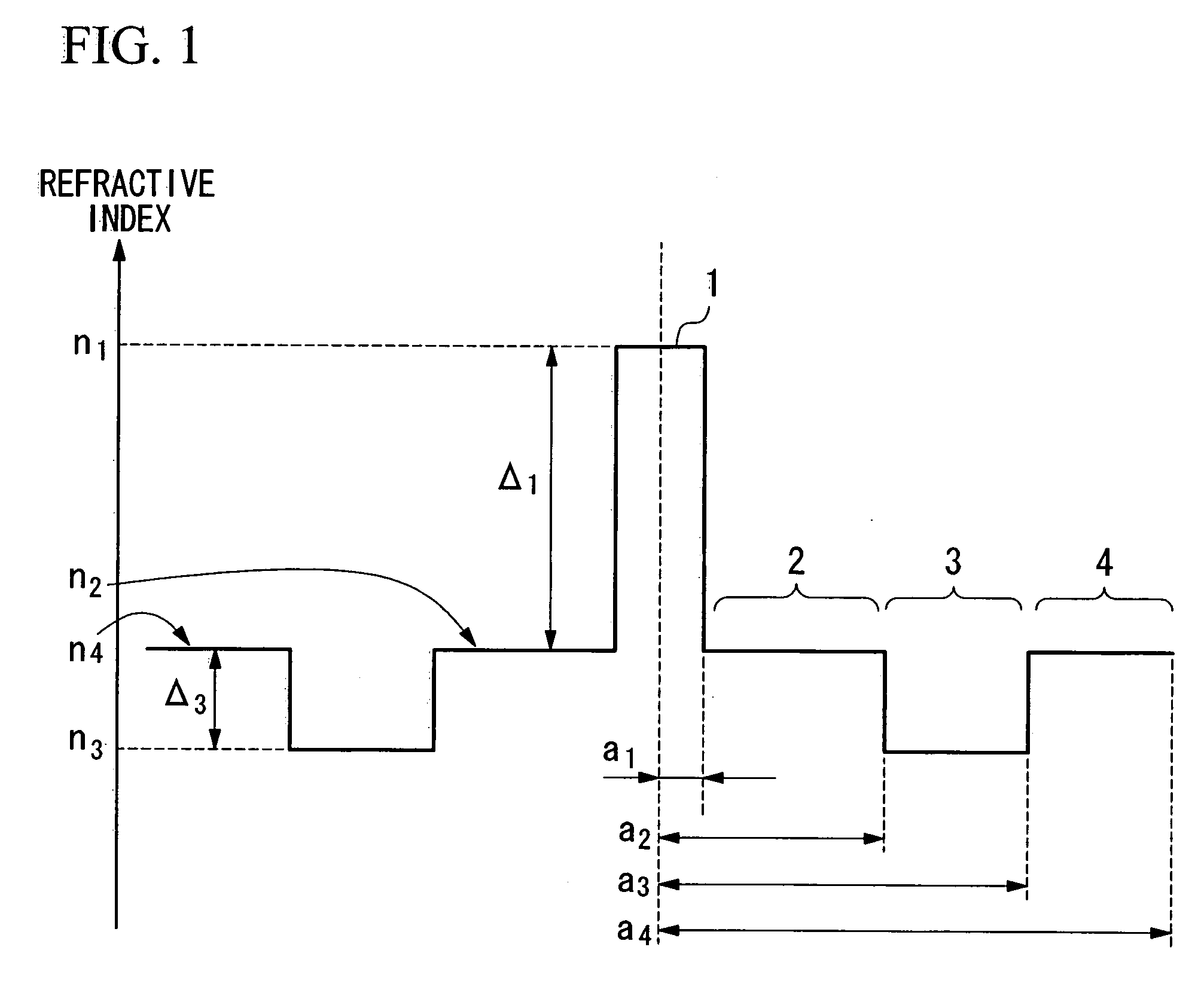
[0110] The radius a1 of the core 1: 3.40 μm

[0111] The radius a2 of the first cladding layer 2: 11.48 μm

[0112] The radius a3 of the second cladding layer 3: 16.45 μm

[0113] The ratio a2 / a1 of the radius of the first cladding layer 2 to the radius of the core 1: 3.37

[0114] The outer diameter of the optical fiber: 125 μm

[0115] The refractive index volume (V) of the second cladding l...

example 3

[0121] The refractive index profile of the optical fiber in this example is shown in FIG. 6.

[0122] The optical fiber of this example was manufactured by forming the region labeled as (a) in the figure using the MCVD method. In the figure, the region (b) is the starting silica tube used in the CVD method. The core material obtained by the MCVD method was subjected to an outside deposition to form the region (c). FIG. 6 shows the result of the refractive index profile of the preform measured using the preform analyzer. As can be seen from this figure, although the refractive index profile of the optical fiber of this example also does not have a perfect step-shaped shape, it can achieve advantageous effects of the present invention.

[0123] Each parameter of the optical fiber of this example was as follows:

[0124] The radius a1 of the core 1: 3.12 μm

[0125] The radius a2 of the first cladding layer 2: 10.30 μm

[0126] The radius a2 of the first cladding layer 2: 16.62 μm

[0127] The rat...


PUM


Abstract

An optical fiber includes: a core at a center; a first cladding layer; a second cladding layer; and a third cladding layer. A maximum refractive index of the core is greater than any of maximum refractive indices of the first cladding layer, the second cladding layer, and the third cladding layer, and the maximum refractive index of the second cladding layer is smaller than any of the maximum refractive indices of the first and the third cladding layer. Additionally, a ratio of a2/a1 is not less than about 2.5 and not more than about 4.5, where a1 represents the radius of the core, and a2 represents the radius of an outer periphery of the first cladding layer, and a relative refractive index difference of the core with respect to a maximum refractive index of the third cladding layer is not less than 0.20% and not more than 0.70%.

Description

CROSS REFERENCE TO RELATED APPLICATIONS [0001] Priority is claimed on Japanese Patent Application No. 2003-107760, filed Apr. 11, 2003, Japanese Patent Application No. 2003-199270, filed Jul. 18, 2003, and Japanese Patent Application No. 2004-18514, filed Jan. 27, 2004, the contents of which are incorporated herein by reference. BACKGROUND OF THE INVENTION [0002] Japanese Patent No. 2618400 describes an optical fiber that includes a cladding layer provided on the periphery of a center core in which the cladding layer has a refractive index groove that has a lower refractive index. It is suggested that optical fibers having such a structure are expected to exhibit various advantageous effects, such as reducing the dispersion slope and lowering the bending loss. However, to achieve such effects, it is desirable that the value of a2 / a1 be between 1.5 and 3.5, where a1 is the radius of the core and a2 is the radius of the inner periphery of the refractive index groove. [0003] Convention...

Claims


Application Information

Patent Timeline
IPC IPC(8): G02B6/036
CPCG02B6/02009G02B6/03688G02B6/03672G02B6/0365G02B6/03611
Inventor MATSUO, SHOICHIROHIMENO, KUNIHARUHARADA, KOICHIIKEDA, MASATAKA
Owner THE FUJIKURA CABLE WORKS LTD
Why Eureka
Try Eureka