Double sided polishing machine

Active Publication Date: 2006-02-23
PETER WOLTERS GMBH
View PDF6 Cites 27 Cited by
  • Summary
  • Abstract
  • Description
  • Claims
  • Application Information

AI Technical Summary

Benefits of technology

[0016] It has already been mentioned that a temperature difference between carrier and polishing disc results in a deformation of the polishing disc and thus to a change of the polishing gap over the radius thereof. If it is taken care that the temperature of the carrier disc is approximately that of the temperature of the polishing disc

Problems solved by technology

It is understood that such measurement of the spacing can be carried out only if no workpiece or a

Method used


Image

  • Double sided polishing machine
  • Double sided polishing machine
  • Double sided polishing machine

Examples


Embodiment Construction

[0020] While this invention may be embodied in many different forms, there are described in detail herein a specific preferred embodiment of the invention. This description is an exemplification of the principles of the invention and is not intended to limit the invention to the particular embodiment illustrated An embodiment example is to be subsequently described with reference to drawings wherein

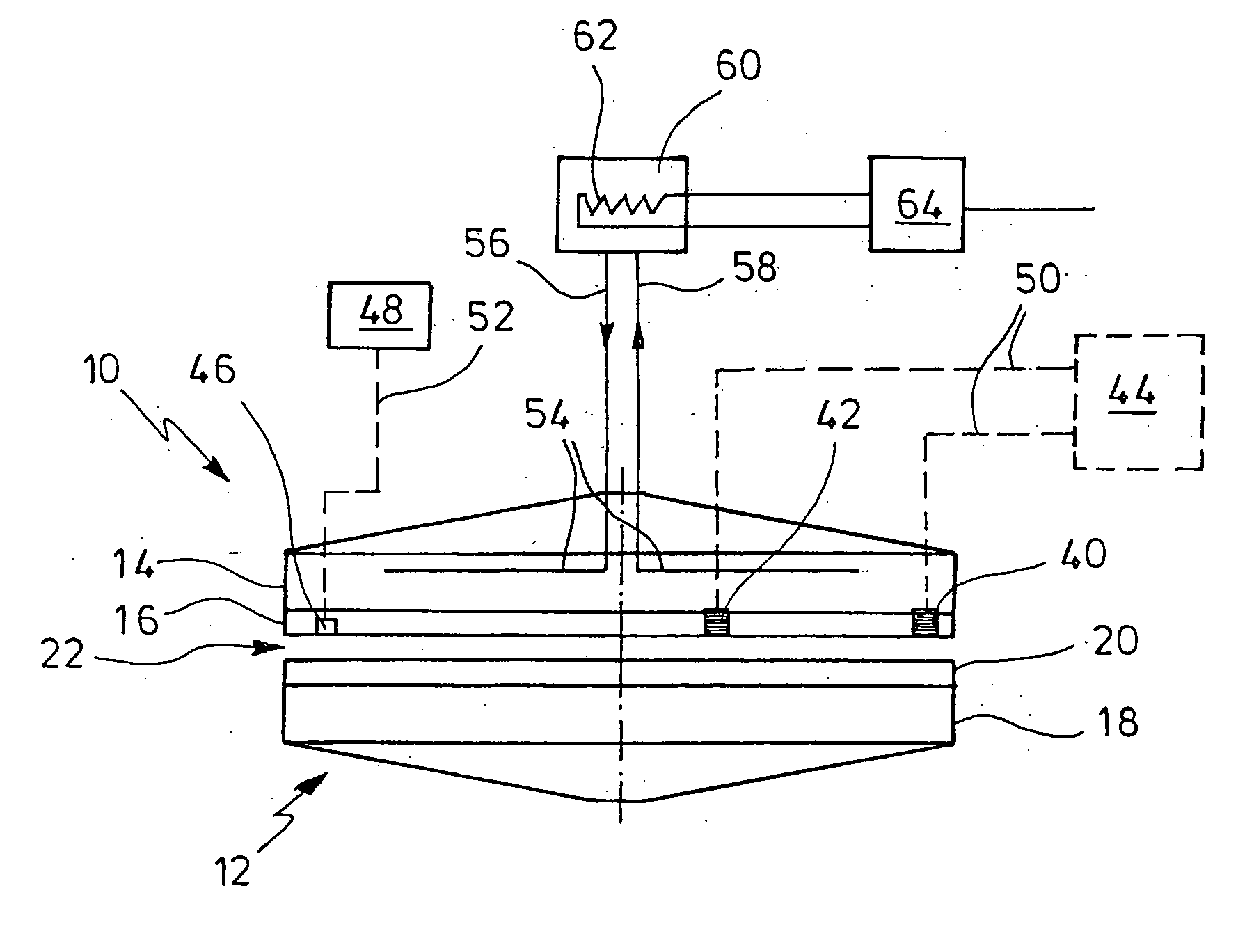
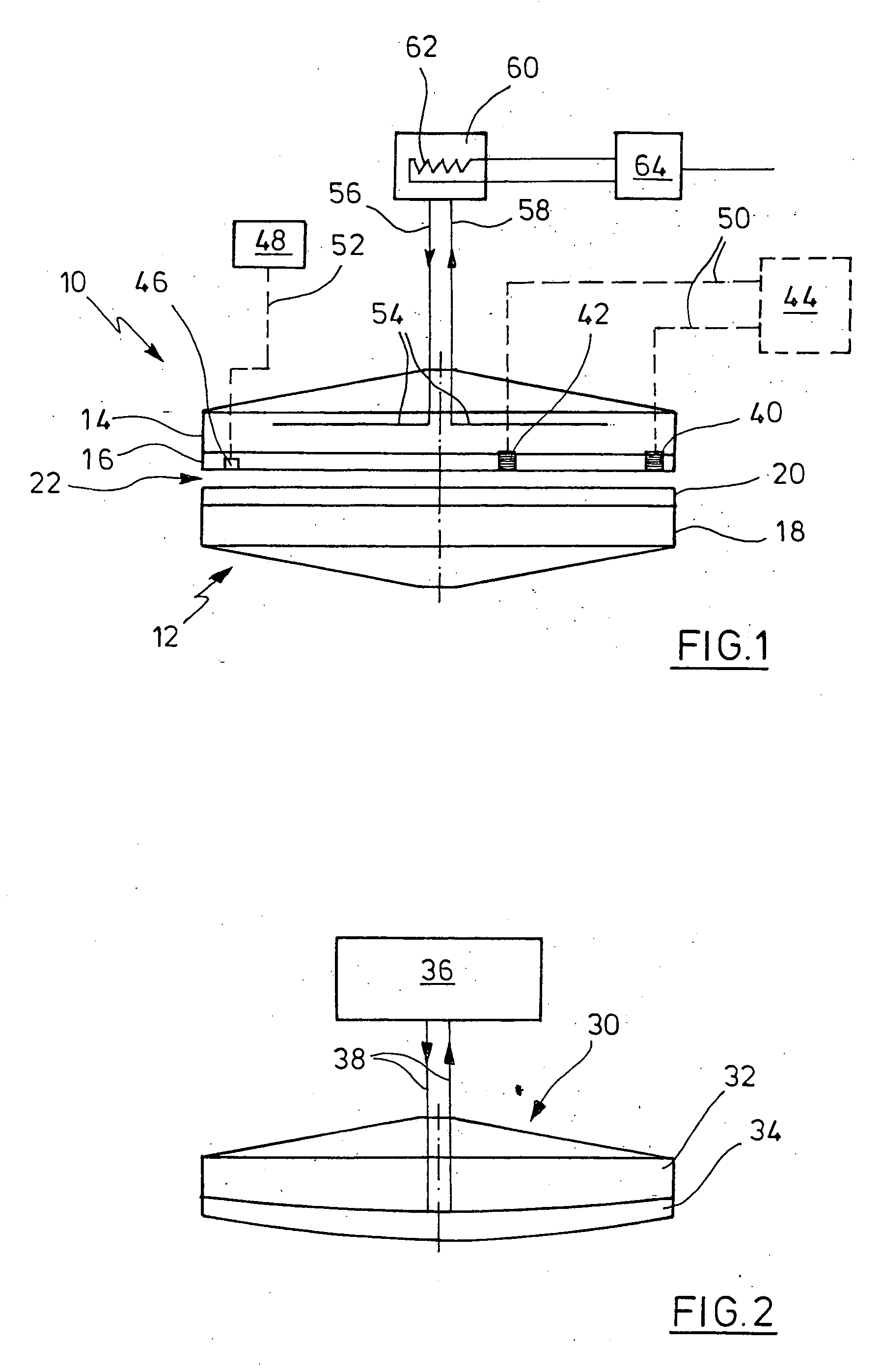
[0021]FIG. 1 shows extremely diagrammatically the working disc of a double-sided polishing machine with means according to the invention;

[0022]FIG. 2 shows the upper working disc of a double-sided polishing machine according to the prior art and

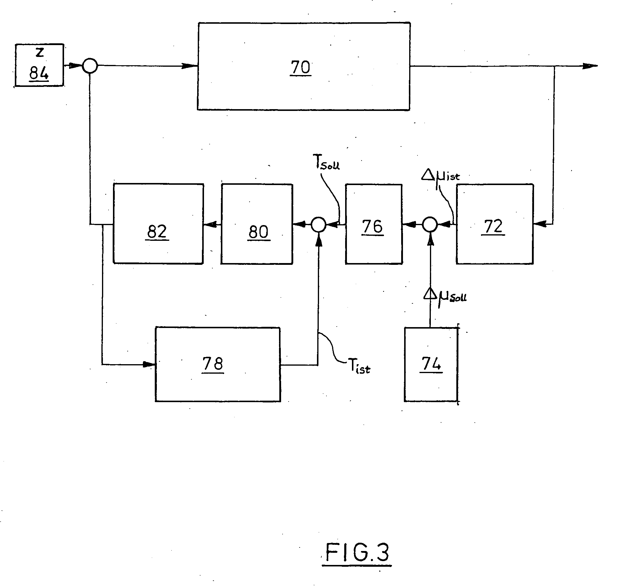
[0023]FIG. 3 shows a circuit for control means for controlling the temperature of the carrier disc of the upper working disc of FIG. 1.

[0024] In FIG. 1 an upper working disc 10 and a lower working disc 12 of a double-sided polishing machine can be seen. All other parts of such a machine are omitted. The upper and the lower working disc 10, 12 ea...


PUM


Abstract

Double-sided polishing machine with an upper and a lower working disc, each comprising a polishing disc and a carrier disc. The working disc are co-axially arranged and rotatable relative to each other, a polishing gap being formed between the polishing discs. Said workpieces are machined in the polishing gap. A temperature control device being at least provided for the upper working disc by which a temperature control fluid can be conveyed through passages in the upper working disc. A spacing measuring device being associated with the working discs which measure the spacing in the polishing gap (gap width μ) at two radial spaced points of the polishing gap.

Description

CROSS-REFERENCE TO RELATED APPLICATIONS [0001] Not applicable. STATEMENT REGARDING FEDERALLY SPONSORED RESEARCH [0002] Not applicable. BACKGROUND OF THE INVENTION [0003] Double-sided polishing machines serve for polishing workpieces having coplanar surfaces, e.g. wafers. The plane parallelism is an essential quality criterion. [0004] A double-sided polishing machine usually has two working discs which are rotationally driven by a shaft, preferably in opposite sense to each other. The shafts are co-axial. Each working disc includes a polishing disc and a carrier disc. Usually, the polishing disc has a steel disc which is firmly secured to the carrier disc. The facing surfaces of the polishing disc are covered by a polishing pad. The flat workpieces are accommodated by openings of so-called runner discs which can be rotationally driven by means of a tooth ring or a pin ring respectively. The workpieces move along a cycloidal path between the working disc or the polishing gap, respecti...

Claims


Application Information

Patent Timeline
IPC IPC(8): B24B49/00B24B37/015B24B37/08
CPCB24B37/08B24B37/015
Inventor ISING, ULRICH
Owner PETER WOLTERS GMBH
Why Eureka
Try Eureka