
Contour follower

a follower and waterjet technology, applied in the direction of instruments, galvano-magnetic hall-effect devices, manufacturing tools, etc., can solve the problems of system shutdown and possibly a damaged workpiece, and the device such as the shield b> of fig. 2 cannot be used concurrently with the contact ring

Active Publication Date: 2006-02-23
FLOW INT
View PDF16 Cites 25 Cited by
  • Summary
  • Abstract
  • Description
  • Claims
  • Application Information

AI Technical Summary

Benefits of technology

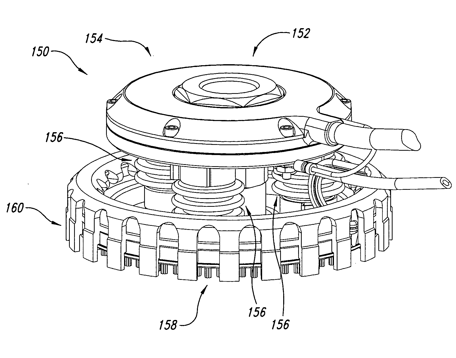
[0049]FIG. 14 shows an enlarged view of a small portion of the contour follower of FIG. 13.

Problems solved by technology

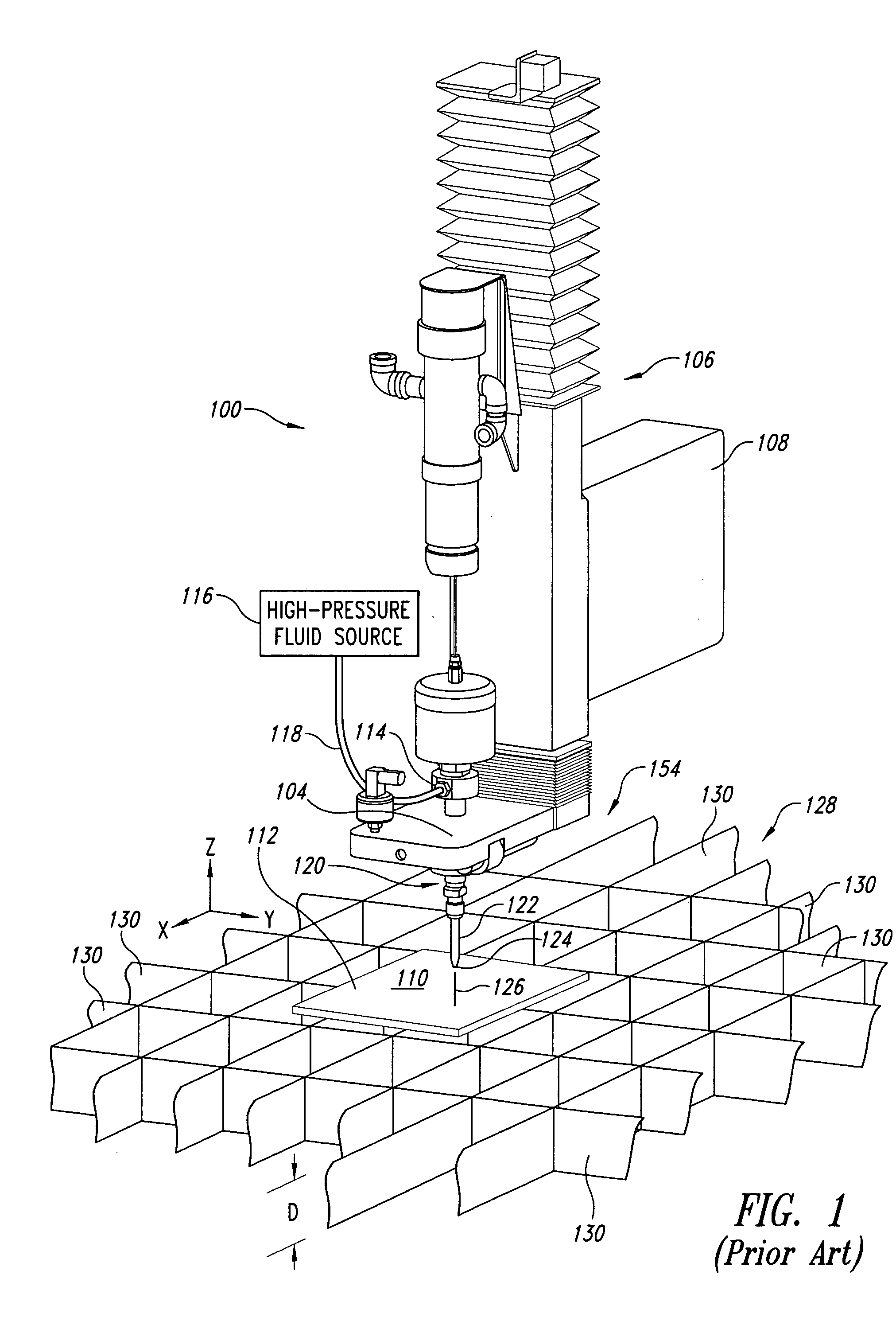
A particular challenge in waterjet cutting systems is the provision of an appropriate support for the workpiece, inasmuch as any surface upon which the workpiece is supported will be subjected to the cutting force of the waterjet 126.
If the standoff distance S is too small, the mixing tube 122 can plug during piercing, causing system shutdown and possibly a damaged workpiece 112.
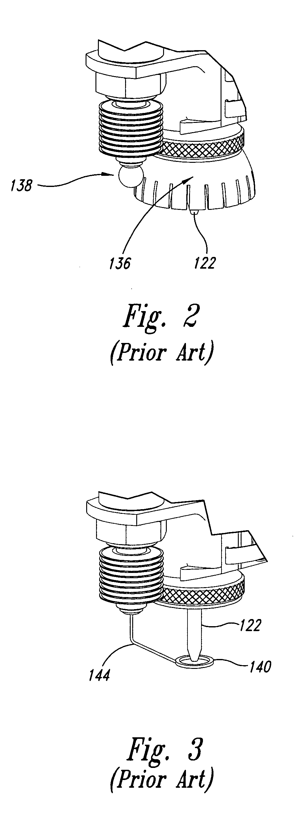
However, a device such as the shield 136 of FIG. 2 cannot be used concurrently with the contact ring 140.
Accordingly, it can be very damaging to components of the cutting system, especially in systems employing abrasives in the fluid stream.
Thus, mixing tubes are a relatively expensive component of the system.
The specially formulated carbides may also be brittle, and can easily break if the mixing tube 122 collides with an obstruction during operation of the cutting system 100, such as fixturing or cut-out portions of the workpiece 112 which may have been kicked up during the cutting operation.
Accidental breakage of the mixing tube 122 increases operational costs and downtime of the cutting system 100.
These two cut characteristics, namely taper and trailback, may or may not be acceptable, given the desired end product.

Method used


Image

  • Contour follower
  • Contour follower
  • Contour follower

Examples


Embodiment Construction

[0050] While many of the challenges associated with waterjet machining have been described in the background section, there is at least one issue that has not yet been addressed. It has previously been assumed, for the purpose of determining the appropriate position of the mixing tube 122, that the upper surface 110 of the workpiece 112 will be substantially horizontal, or will lie in a plane that is parallel to the X-Y plane. Most sensors configured to determine the position of the upper surface 110 make that determination prior to the beginning of a cutting operation, such as the sensor described with reference to FIG. 2. Even in the case of the sensor described with reference to FIG. 3, which can be configured to continually track the surface 110 of the workpiece 112 as the cutting operation progresses, such a sensor can only detect changes in height of the upper surface 110, and cannot determine the angle of that surface, with respect to the X-Y plane.

[0051] Accordingly, errors...


PUM

PropertyMeasurementUnit
thicknessesaaaaaaaaaa
lengthaaaaaaaaaa
distanceaaaaaaaaaa

Abstract

A contour follower includes a plurality of sensors spaced around a waterjet nozzle, each of the sensors being configured to measure a distance between a working surface and a first plane, perpendicular to a longitudinal axis of the nozzle. The sensors may include hall-effect sensors lying in the first plane and magnets lying in a second plane, parallel to the working surface. A detecting circuit processes signals from the sensors to determine an angle of the working surface, relative to the first plane, and a distance between an aperture of the nozzle and the working surface. A collision detection sensor provides a signal in the event the device approaches to within a selected distance of an obstruction in the plane of the working surface. A shield plate blocks and dampens secondary spray-back of cutting fluid occurring at low angles above the working surface.

Description

BACKGROUND OF THE INVENTION [0001] 1. Field of the Invention [0002] This invention is related, generally, to waterjet cutting systems, and, in particular, to a method and apparatus for controlling the orientation and position of a waterjet cutting head with respect to a surface. [0003] 2. Description of the Related Art [0004] Waterjet and abrasive-jet cutting systems are used for cutting a wide variety of materials, including stone, glass, ceramics, and various metals, including stainless steel. Such systems are capable of cutting material thicknesses ranging up to and exceeding two inches. Thinner material may be stacked for cutting multiple pieces simultaneously. [0005] In a typical fluid jet cutting system, a high-pressure fluid (e.g., water) flows through a cutting head having a cutting nozzle that directs a cutting jet onto a workpiece. The system may draw an abrasive into the high-pressure fluid jet to form an abrasive jet. The cutting nozzle may then be controllably moved acr...

Claims


Application Information

Patent Timeline
Patent Type & Authority Applications(United States)
IPC IPC(8): B24C1/00
CPCB23Q17/2233B24C1/086B26F3/004B26D7/2628B26D7/22Y10T83/0591
Inventor SCIULLI, FELICE M.MEYER, ANDREASMANN, ROBERT J.KNAUPP, MICHAELWAKEFIELD, CHARLES M.RAGHAVAN, CHIDAMBARAMSTERNE, ANDREW P.ERICHSEN, GLENN A.
Owner FLOW INT
Learn More