
Cover

a technology of cover and cover plate, applied in the field of cover plate, can solve the problems of not being able to adjust the shielding, the adhesive effect is stopped, and the risk of bacteria and soil collected thereon entering the construction is reduced, and the risk of the infusion device being torn off is minimised. , the surface is smooth and the effect of reducing the risk of bacteria and soil collecting thereon entering the construction

Inactive Publication Date: 2006-02-23
UNOMEDICAL AS
View PDF99 Cites 81 Cited by
  • Summary
  • Abstract
  • Description
  • Claims
  • Application Information

AI Technical Summary

Benefits of technology

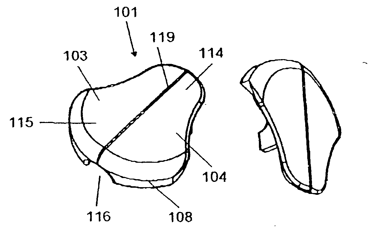
[0006] It is thus the object of the present invention to provide a cover that remedies the problems that may occur in connection with the prior art covers and whereby complete or partial shielding of the upper free face of the infusion set is enabled, but wherein the lower face is unshielded and the side faces are also partially unshielded, and wherein a shielding of the plate takes place directly on the infusion device. Hereby it is obtained that the risk of bacteria and soil collected thereon penetrating into the construction is reduced considerably, and likewise the cover enables a smoother surface with an ensuing minimisation of the risk of the infusion device being torn off.
[0008] Thus, the cover functions in that, by means of its attachment means that are provided on the lower free face, it fits into the upper face of the infusion device and by a press fitting ensures that the cover is securely attached onto the infusion device due to the clamping effect obtained between the individual attachment means and can be reinforced by the infusion device preferably comprising, as described in the attached claims, a side flange, and wherein this side flange cooperates with the attachment means to bring about a secure attachment of the cover on the infusion device.
[0010] In one embodiment of the present invention, the cover further comprises a flange that forms a first angle in relation to the upper plate and is connected thereto, in case the infusion device that consists of two parts is separated it is possible—due to the presence of the flange—for the cover to remain in place on the part designated the cannula part; the attachment means and the flange bringing about a squeezing effect that secures the cover in position.
[0011] In another embodiment of the present invention, the cover includes a face of the flange facing towards outer side faces of the infusion device that is congruent therewith, thus an optimal complete or partial shielding of the infusion device is obtained.
[0012] In yet another embodiment of the present invention, a cover is provided wherein the expanse of the upper plate element is smaller than the expanse of the upper face of the infusion device, and wherein the flange extends partially around the side faces of the infusion device which makes it possible to seize the exposed parts of the infusion device and thus to carry out a separation thereof.
[0014] In yet another embodiment of the present invention, a cover is provided wherein the attachment means are male parts and that the elements on the infusion device are provided by recesses, the attachment means further comprise at least two protruding plate elements located at a second mutual distance, and the protruding plate elements comprise rectangular plate-shaped elements extending perpendicularly to the lower face that bring about a convenient shape of the attachment means.

Problems solved by technology

In connection with an infusion device being located on the skin, it is known to shield it; such shielding, however, involving a complete covering of the infusion device and in such a manner that it becomes inaccessible to manipulation from the outside.
However the construction necessitates use of an additional frame for securing the infusion device and also for securing the dome that shields the entire infusion device and is also manufactured to be very voluminous.
There is thus a risk of it being torn off during use and, likewise, it prevents access to the infusion device and, furthermore, there is a risk of the adhesive effect ceasing and, likewise, it cannot be expected that adjustments of the shielding are possible as the adhesive effect will cease.

Method used


Image

  • Cover
  • Cover
  • Cover

Examples


Embodiment Construction

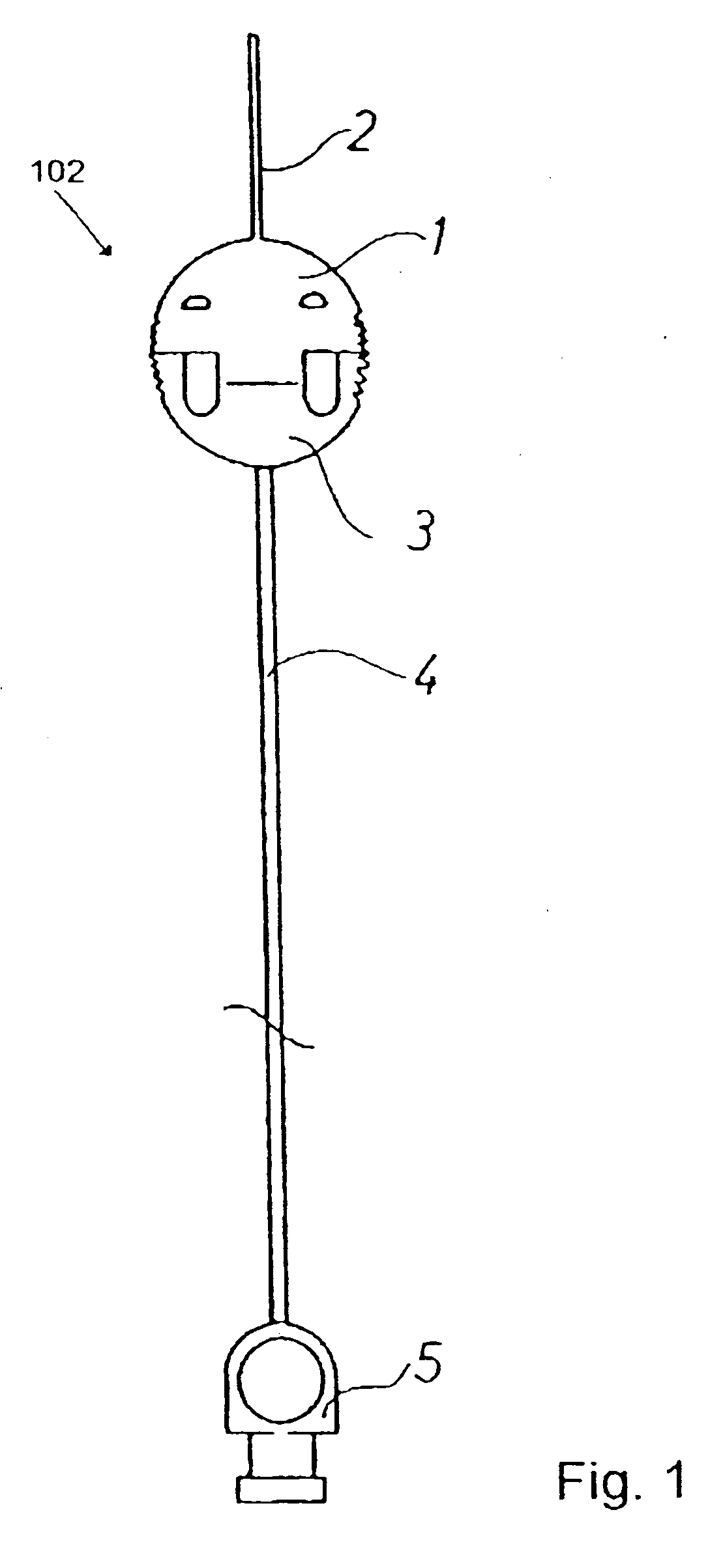
[0024] The infusion set of FIG. 1 comprises a cannula housing 1 with a soft cannula 2 secured therein and manufactured in a conventional manner of a suitable plastics material. The infusion set further comprises a connecting hub 3 connected in a conventional manner through a hose 4 with a lower coupling member 5 to be used for the coupling thereof to an insulin pump (not shown).

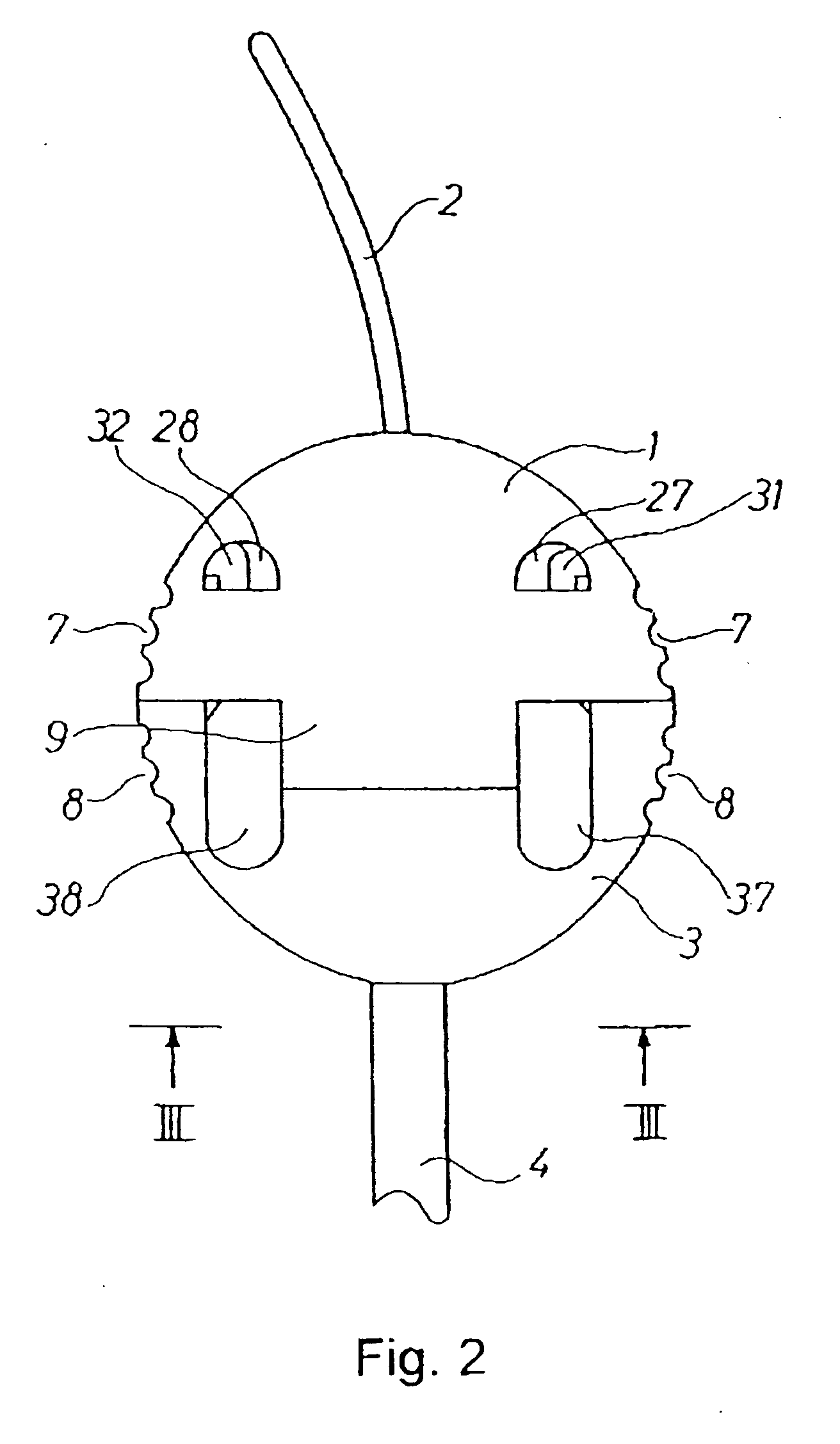
[0025]FIG. 2 shoves the cannula housing 1 and the connecting hub 3 on a larger scale and creating the infusion device 102. It appears clearly that together they are of a relatively flat shape and of a uniform thickness and have a substantially plane rear side. When seen from the top, they are together of a substantially circular shape, said shape being interrupted only by recesses 7 and 8, respectively, for facilitating a finger-handling. As illustrated in FIG. 2, the cannula housing 1 and the connecting hub 3 are divided substantially along a diametrical central plane, a central projection 9 being provided ...


PUM


Abstract

A cover (101) for being located on an infusion device, which cover (101) comprises an upper plate element (103) with an upper face (104) and a lower face (105) oriented towards the upper face of the infusion device, wherein the lower face (105) of the plate element (103) comprises attachment means (106), which means cooperate with elements on the infusion device. Hereby the risk of bacteria and soil collected thereon penetrating into the construction, is reduced considerably, and likewise the cover yields a smoother surface with an ensuing minimisation of the risk of the infusion device being torn off.

Description

[0001] This application is a continuation application of application Ser. No. 10 / 366,453, pending, filed on Feb. 12, 2003, the entirety of this reference is incorporated herein.FIELD OF THE INVENTION [0002] The invention relates to a cover for being located on an infusion device, said cover comprising an upper plate element with an upper face and a lower face oriented towards the upper face of the infusion device. BACKGROUND [0003] In connection with an infusion device being located on the skin, it is known to shield it; such shielding, however, involving a complete covering of the infusion device and in such a manner that it becomes inaccessible to manipulation from the outside. [0004] One example of this is known for instance from WO 87 / 06474. This discloses a device that can be strapped to the body over the location of insertion of an intravenous needle to shield the puncture area against contact and for anchoring the tube so that the needle will not be pulled out inadvertently. ...

Claims


Application Information

Patent Timeline
IPC IPC(8): A61M31/00A61M5/158A61M25/02
CPCA61M5/158A61M2005/1587A61M25/02
Inventor JENSEN, SOREN
Owner UNOMEDICAL AS
Learn More