Directional probe treatment apparatus

a treatment apparatus and a technology of directional probes, applied in the field of directional probe treatment apparatus, can solve the problems of limited use of straight cannulas by ophthalmic surgeons to help introduce instruments into the globe, and higher mechanical failure rates of instruments during use, and achieve the effect of ensuring structural integrity

Active Publication Date: 2006-02-23
IRIDEX CORP
View PDF10 Cites 14 Cited by
  • Summary
  • Abstract
  • Description
  • Claims
  • Application Information

AI Technical Summary

Benefits of technology

[0006] In one embodiment of the present invention, a directional probe is provided that has the durability and consistent geometry of a rigid instrument. The directional probe may be designed so that it does not have moving parts which helps to ensure structural integrity of the inserted portion of the instrument. In yet another embodiment, a directional probe may have a monolithic geometry which is stronger than hardware employing flexible or deformable features and simultaneously provides angulation and cannula compatibility.

Problems solved by technology

Ophthalmic surgeons using straight cannula to help introduce instruments into the globe have been limited to date to the use of straight, rigid instruments, or too deformable (“directional”) instruments.
The small dimensions associated with devices used in ophthalmic and other microsurgeries can result in higher rates of mechanical failure of instruments during use.

Method used


Image

  • Directional probe treatment apparatus
  • Directional probe treatment apparatus
  • Directional probe treatment apparatus

Examples


Embodiment Construction

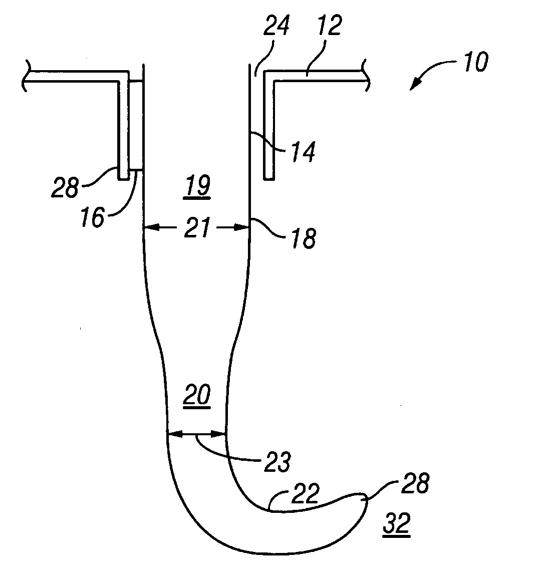
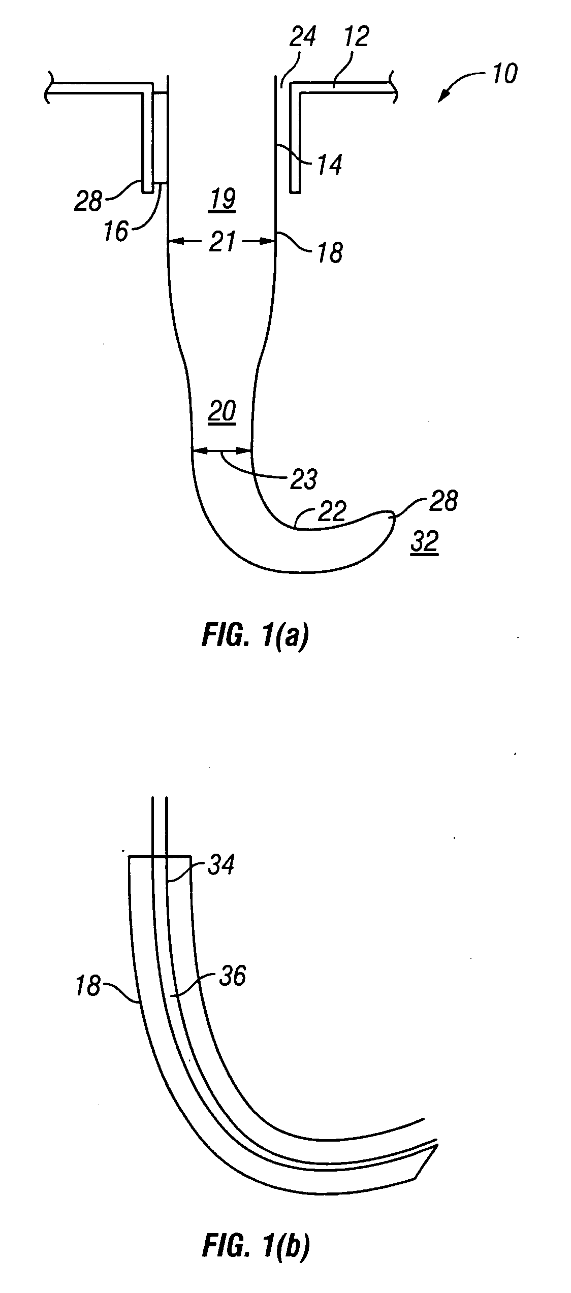
[0018] Referring to FIG. 1, one embodiment of the present invention is a directional probe, generally denoted as 10, that has a cannula 12 with a cannula lumen 14. Cannula lumen 14 has an average diameter 16. In one embodiment, average diameter 16 is about from 20-25 gauge. 20 and 25 gauge are both important in ophthalmic surgery. Dimensions much smaller than 25 gauge, higher gauge number, such as 26 gauge, 27, gauge are less important due to incompatibility with existing support instrumentation and the increasing difficulty coupling therapeutic modalities such as laser, electrosurgery, diathermy, and the like.

[0019] A probe 18 is positionable in cannula lumen 14. Probe 18 has a first section 19 with a first average diameter 21, a distal portion 20 with a curved section 22 that has at least one radius of curvature and with a second average diameter 23. In one embodiment second average diameter is the range of about 20-30 gauge. Second average diameter 23 is less than first average ...


PUM


Abstract

A treatment apparatus includes a cannula with a cannula lumen. The cannula has a first average diameter. A probe is positionable in the cannula lumen. The probe has a first section with a second average diameter and a second section with a third average diameter that is less than the second average diameter. At least a portion of the second section has a curved section with at least one radius of curvature. The radius of curvative is selected to provide that as the second section passes through the cannula lumen a first side of the second section is tangential to a first side of the cannula lumen, and a second opposing side of the second section is tangential to a second opposing side of the cannula lumen.

Description

[0001] This application claims the benefit of priority to U.S. Provisional Application Ser. No. 60 / 602,166 filed Aug. 16, 2004 and is fully incorporated herein by reference for all purposes.BACKGROUND OF THE INVENTION [0002] Ophthalmic surgeons using straight cannula to help introduce instruments into the globe have been limited to date to the use of straight, rigid instruments, or too deformable (“directional”) instruments. Such instruments must first pass through the cannula in an essentially straight configuration. The instrument is then deflected into some angle that is controlled by the surgeon. [0003] The small dimensions associated with devices used in ophthalmic and other microsurgeries can result in higher rates of mechanical failure of instruments during use. [0004] There is a need for a directional probe that has the durability and consistent geometry of a rigid instrument. There is a further need for a directional probe that does not have moving parts which helps to ensu...

Claims


Application Information

Patent Timeline
Patent Type & Authority Applications(United States)
IPC IPC(8): A61F2/00
CPCA61B17/3421A61B17/3468A61B18/082A61F9/007A61B19/201A61B2017/003A61B2017/320044A61B18/148A61B90/11
Inventor BUZAWA, DAVID M.
Owner IRIDEX CORP
Why Eureka
Try Eureka