Eureka AIR delivers breakthrough ideas for toughest innovation challenges, trusted by R&D personnel around the world.

Yarn quality assurance method and yarn processing machine

a quality assurance method and yarn processing technology, applied in the direction of yarn, textiles and paper, etc., can solve the problems of crimping of the product fancy yarn, complex system development, and automatic change of the feeding spool

Inactive Publication Date: 2006-03-02
SSM SCHIRER SCHWEITER METTLER AG
View PDF4 Cites 13 Cited by
  • Summary
  • Abstract
  • Description
  • Claims
  • Application Information

AI Technical Summary

Benefits of technology

[0023] With the method according to the invention, the thread tension in the unwinding region is stabilised so that a regular thread tension profile is maintained over time regardless of the process speed and the diameter of the feeding spool. This ensures a uniform quality of the product multifilament yarn, e.g. the textured yarn over the entire length of the POY yarn, for example, on the feeding spool. Further, an increase in the production speed of the manufacturing process is achieved for the same yarn quality.
[0024] The method according to the invention makes it possible to achieve complete “online” control of the thread tension during unwinding of the yarn from the feeding spool. The thread tension can be kept constant regardless of the quality of the yarn, the diameter of the feeding spool, and the selected unwinding speed. In addition to the possibility of increasing or reducing the thread tension during winding in a controlled fashion if necessary, the thread tension can be permanently reduced whereby a higher production speed and efficiency can be achieved.
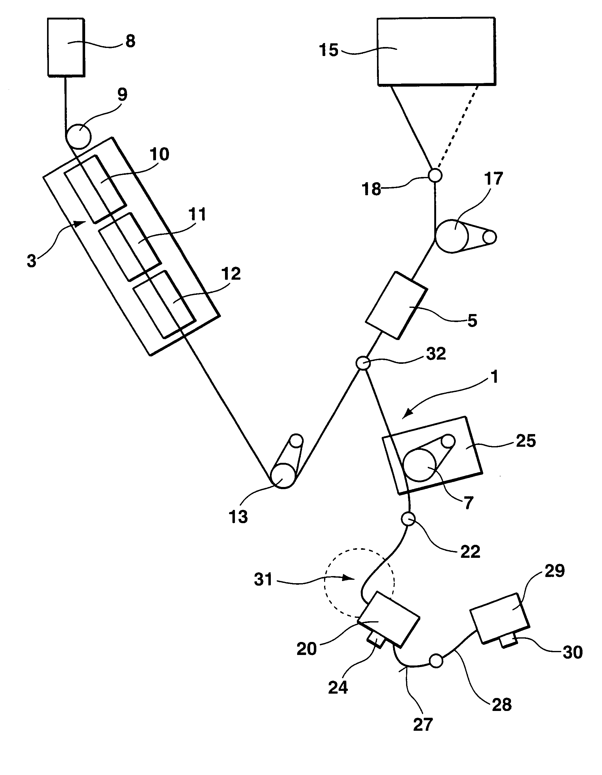
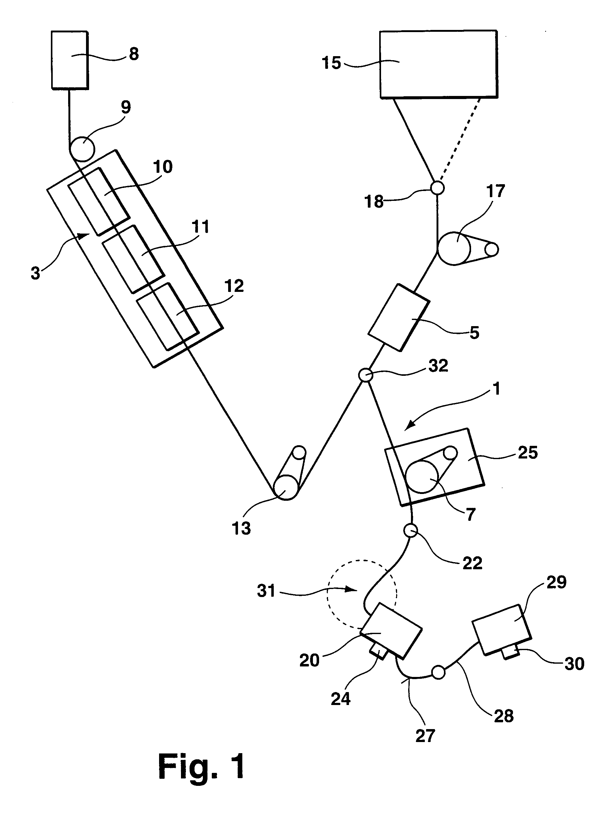
[0027] The method according to the invention allows the elastic yarn to be taken off overhead since the fluctuations in thread tension which occur are compensated. If the elastic yarn is taken off overhead in an air-covering process, interruptions of the production process caused by changing the feeding spool can be avoided. During overhead take-off the feeding spool itself does not rotate so that during overhead take-off it is possible to work with a reserve feeding spool which can be used immediately so that downtimes of a suitably operating yarn processing machine can be minimised. The reserve feeding spool is positioned symmetrically to the vertical axis of the yarn processing machine with the feeding spool from which the elastic yarn is currently being taken off. The free end of the yarn on the reserve feeding spool is knotted with the terminating end of the yarn on the feeding spool currently being unwound. When the yarn on the feeding spool currently being unwound is used up, the yarn of the reserve feeding spool is automatically taken off and the manufacturing process continues without interruption. The empty feeding spool is then replaced by a new feeding spool which is used as the new reserve feeding spool where the yarn of the new feeding spool is accordingly knotted with that of the old reserve feeding spool. An almost continuous process is thereby achieved.
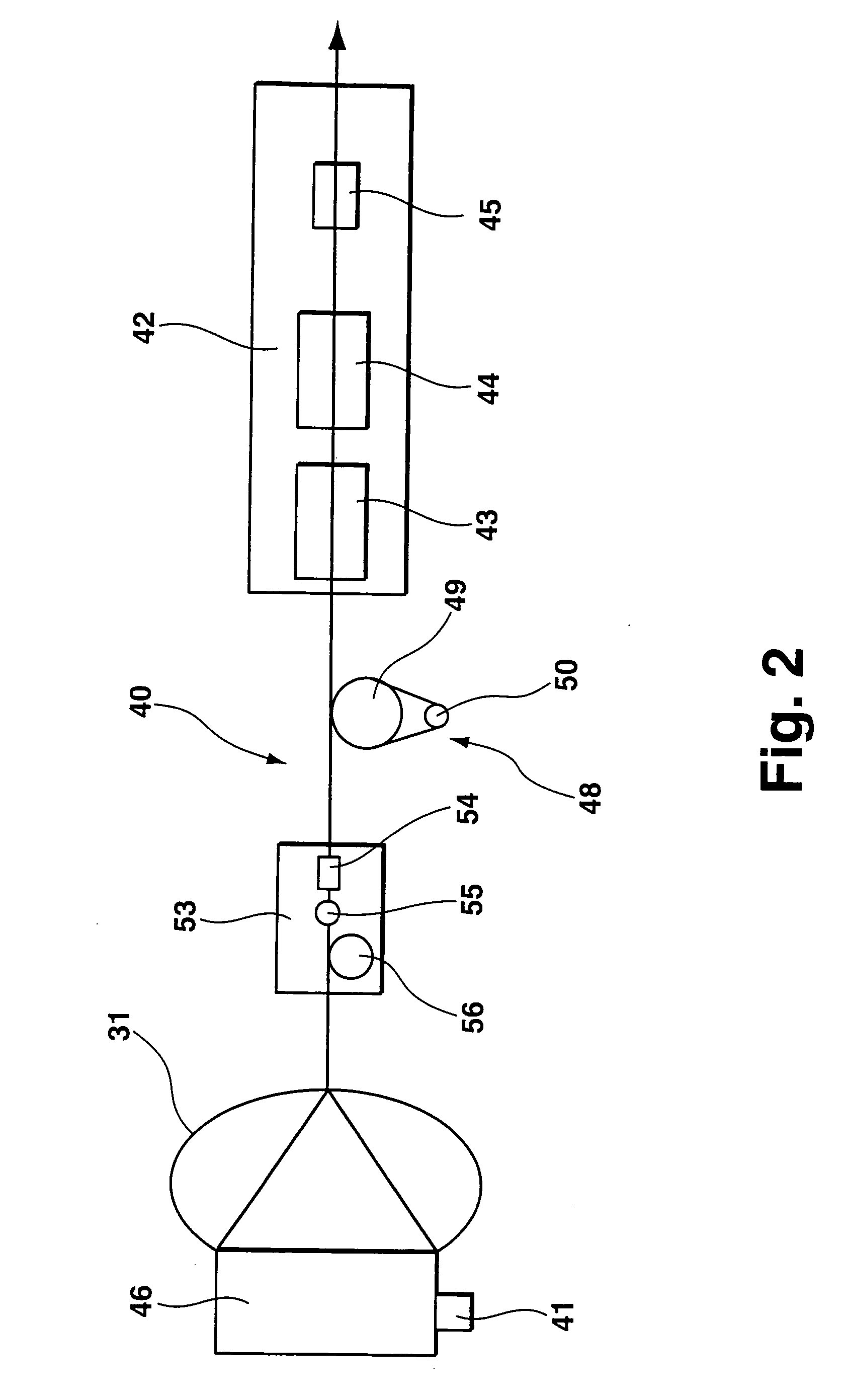
[0029] A yarn processing machine according to the invention has at least one feeding spool receiver set up to receive respectively at least one feeding spool from which yarns can be taken off and a multifilament yarn manufacturing unit to which yarns can be supplied from the feeding spools via thread runs with respectively one thread tension. According to the invention, a thread tension regulating module comprising a thread tension sensor is arranged in at least one controlled thread run between the relevant feeding spool receiver and the multifilament yarn manufacturing unit, wherein the thread tension regulating module preferably comprises a thread brake and / or controllable feeder rolls. The thread tension regulating module is set up to derive a control value from a thread tension measured by a thread tension sensor and keep the thread tension constant in a predetermined thread tension range. The yarn quality assurance method according to the invention can be implemented using the yarn processing machine according to the invention. The yarn processing machine according to the invention thus provides the advantages of the yarn quality assurance method according to the invention.
[0031] The multifilament yarn manufacturing unit preferably comprises an air-covering nozzle wherein preferably feeder rolls and / or at least one thread guiding device are provided in the thread run before the air-covering nozzle and wherein a feeding spool receiver is set up in the controlled thread run to take off overhead a highly elastic yarn from a feeding spool taken up by the feeding spool receiver. The feeder rolls can be part of the thread tension regulating module. The thread guiding device makes it possible to always supply the highly elastic yarn from the same position from the thread tension regulating module. This is especially advantageous during overhead unwinding of the elastic yarn from the feeding spool since interruption of the manufacturing process by changing the feeding spool can be avoided during overhead unwinding by means of a reserve feeding spool, where the reserve feeding spool can be held ready in another feeding spool receiver.

Problems solved by technology

In order to interrupt the production process only as briefly as possible when the feeding spool needs to be changed, e.g., when the current feeding spool is used up, complex systems have been developed for changing the feeding spool automatically.
Freely-rotating take-off can only be used at low process speeds.
After cooling the latent torsional forces have an effect and result in crimping of the product fancy yarn.
If the friction relationships between the filament yarns and the false twist spindle vary, that is if process fluctuations or instabilities occur, this then results in a non-uniform yarn structure or defects in the yarn and thus in loss of quality in the yarn produced.
Such defects or disturbances can, for example, result from disturbances in the spinning mill, from non-uniform application or non-uniform adjustment of the spinning preparation on the thread surface, from temperature fluctuations during texturing or from contamination e.g. in the heater and / or in the cooling rail.
The disturbances can bring about a so-called ballooning of the yarn which occurs particularly at high rotation speeds and the high thread tensions associated therewith.
Ballooning of the yarn results in an uncontrolled run of thread and fluctuations in the thread tension.
This twist slippage leads to a twist deficit inside the twist zone, i.e., the twist density, that is the number of twists per unit length of filament yarn fluctuates.
This results in short closed yarn sections, so-called “tight spots” and long non-uniformly textured yarn sections which is called surging.
In addition, the stretching values fluctuate and the dyeing is unsatisfactory.
In force-locking false twist spindles according to the prior art, the twist density produced cannot be controlled very exactly, and this results in process-technology production limitation of the surging and therefore ballooning of the thread in the twist zone with associated thread tension fluctuations which in turn results in twist fluctuations.
Another factor which limits the production speed in false twist texturing processes is the unwinding speed of the yarns, e.g. a partially oriented multifilament yarn (POY), from the feeding spool.
These problems appear particularly severely especially with polyamide (PA) yarns.
This is not sufficient to avoid the variations of the thread tension during the manufacturing process which have been described.

Method used


Image

  • Yarn quality assurance method and yarn processing machine
  • Yarn quality assurance method and yarn processing machine
  • Yarn quality assurance method and yarn processing machine

Examples


Embodiment Construction

[0035] The figures in the drawings show the subject matter of the invention highly schematically and should be understood as not being to scale. The individual components of the subject matter according to the invention are represented so that their structure can be clearly shown.

[0036]FIG. 1 shows a controlled thread run 1 in a yarn processing machine according to the invention by which means an air-covering method is executed using an elastic yarn and a yarn produced in a false twist texturing unit 3 as covering thread. The method according to the invention is shown for the example of a yarn processing machine which produces a covering thread for air-covering by means of false twist texturing. The method according to the invention and especially the preferred embodiment of the supply of an elastic yarn as controlled yarn to an air-covering unit 5 as a multifilament yarn manufacturing unit via actively driven feeder rolls 7 and the overhead unwinding of the elastic yarn used in th...


PUM

PropertyMeasurementUnit
speedsaaaaaaaaaa
total lengthaaaaaaaaaa
tensionaaaaaaaaaa

Abstract

A yarn quality assurance method and a yarn processing machine set up for implementing the method according to the invention is proposed comprising at least one feeding spool receiver 24, 30 set up to receive respectively at least one feeding spool 20, 29 from which yarns can be taken off, and a multifilament yarn manufacturing unit 5 to which yarns are supplied from the feeding spools 20, 29 via thread runs with respectively one thread tension. According to the invention, a thread tension regulating module 25 with a thread tension sensor is arranged in at least one controlled thread run 1 between the relevant feeding spool receiver 24 and the multifilament yarn manufacturing unit 5, wherein the thread tension regulating module 25 is set up to derive a control value from a thread tension measured by the thread tension sensor and to keep the thread tension constant in a predetermined thread tension range.

Description

BACKGROUND OF THE INVENTION [0001] The invention relates to a yarn quality assurance method when manufacturing a multifilament yarn and a yarn processing machine for implementing the yarn quality assurance method. The yarn quality assurance method comprises the process steps of taking off at least one thread from respectively one feeding spool and supplying the yarn via a run of thread into a multifilament yarn manufacturing unit, wherein the yarns are held at a thread tension. The yarn quality assurance method is suitable in principle for use in any multifilament yarn manufacturing method e.g., in draw-winding or weaving, but especially for use in texturing methods, especially false twist texturing methods and / or air covering methods. [0002] Machines with an air-covering nozzle (air-covering machine) are used to process filament yarns together permanently to form a multi-component yarn (air-covering yarn) by means of an air jet (interlacing jet). In this case, at least one covering...

Claims


Application Information

Patent Timeline
Patent Type & Authority Applications(United States)
IPC IPC(8): D01H13/26
CPCD02G1/167D02G1/0266D01H13/10D01H13/16
Inventor MACCABRUNI, DAVIDEGUTBROD, ROBIN
Owner SSM SCHIRER SCHWEITER METTLER AG
Why Eureka
Eureka Blog
Learn More