Bypass duct fluid cooler

a technology of duct fluid cooler and bypass duct, which is applied in the direction of machines/engines, vessel construction, marine propulsion, etc., can solve problems such as engine operation problems, and achieve the effect of light weigh

Active Publication Date: 2006-03-02
PRATT & WHITNEY CANADA CORP
View PDF21 Cites 65 Cited by
  • Summary
  • Abstract
  • Description
  • Claims
  • Application Information

AI Technical Summary

Benefits of technology

[0008] The present invention advantageously provides a cooling apparatus and method for cooling, for example, the lubricating oil used in a bypass gas turbine engine in an effective manner, and the cooling apparatus is light weight and relatively simple.

Problems solved by technology

Without proper cooling, poor cooling and / or lubrication of gear and bearings results which may cause problems for engine operation.

Method used


Image

  • Bypass duct fluid cooler
  • Bypass duct fluid cooler
  • Bypass duct fluid cooler

Examples


Embodiment Construction

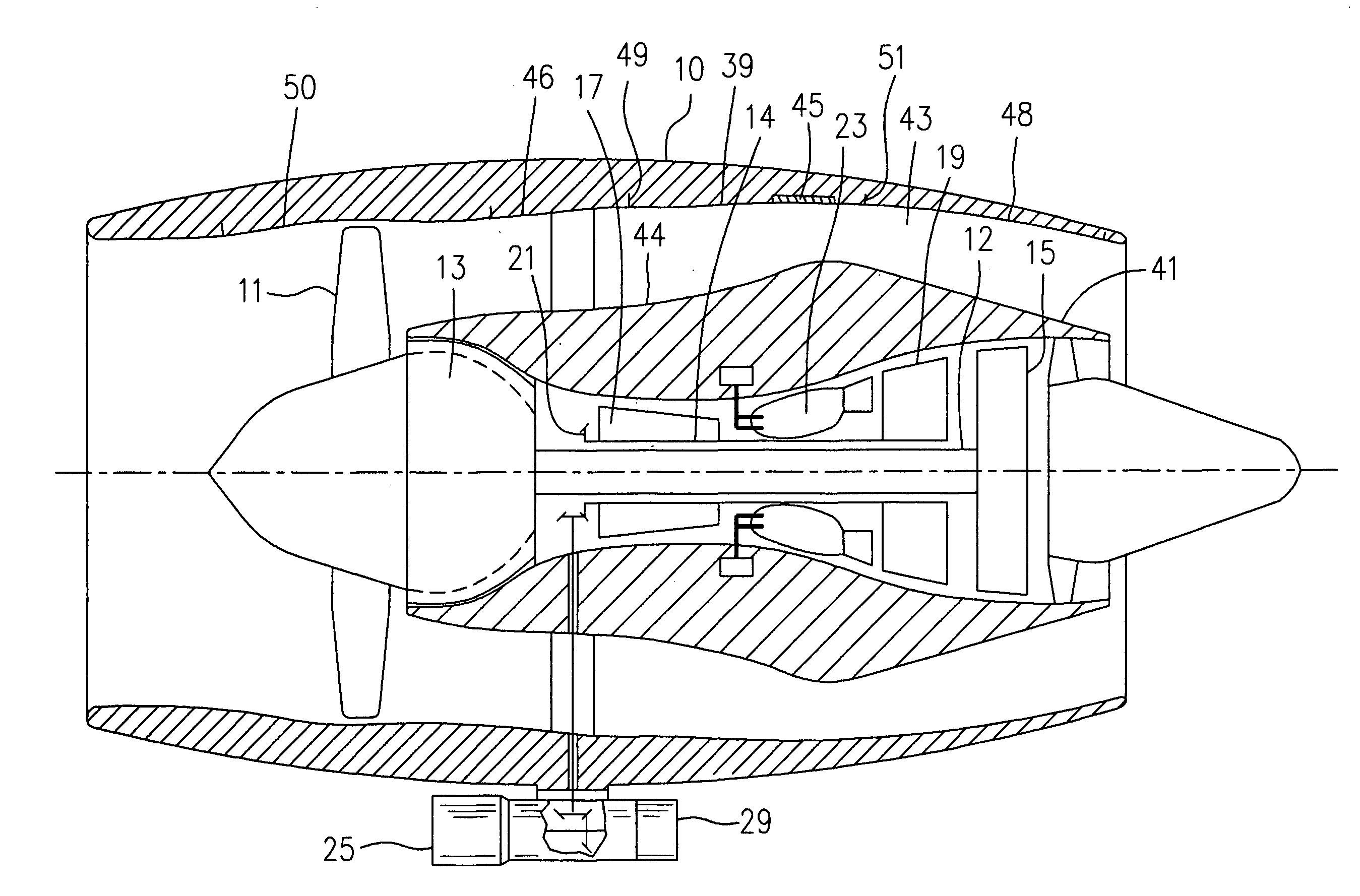
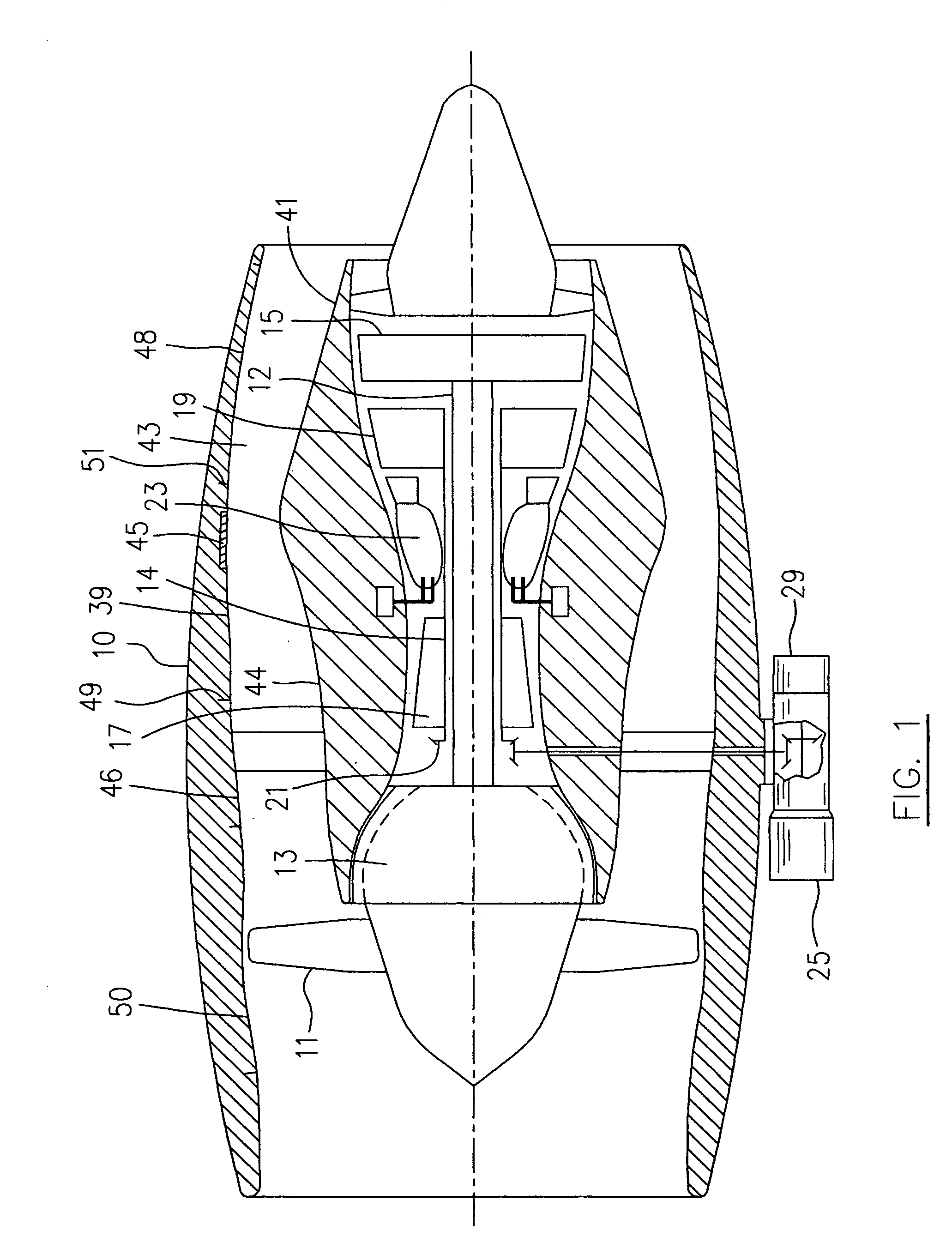
[0015] A bypass gas turbine engine seen generally in FIG. 1 includes a housing nacelle 10, a low-pressure spool assembly seen generally at 12 which includes a fan 11, a low-pressure compressor 13 and a low-pressure turbine 15, a high-pressure spool assembly seen generally at 14 which includes a high-pressure compressor 17, a high-pressure turbine 19 and a gear 21, a combustor 23 and an accessory-drive assembly 25. An annular bypass duct 43 is defined between an inner bypass duct wall 44 and an outer bypass duct wall 39. A stream of bypass air which is compressed by the fan 11, is directed through the annular bypass duct 43 and discharged therefrom to produce thrust.

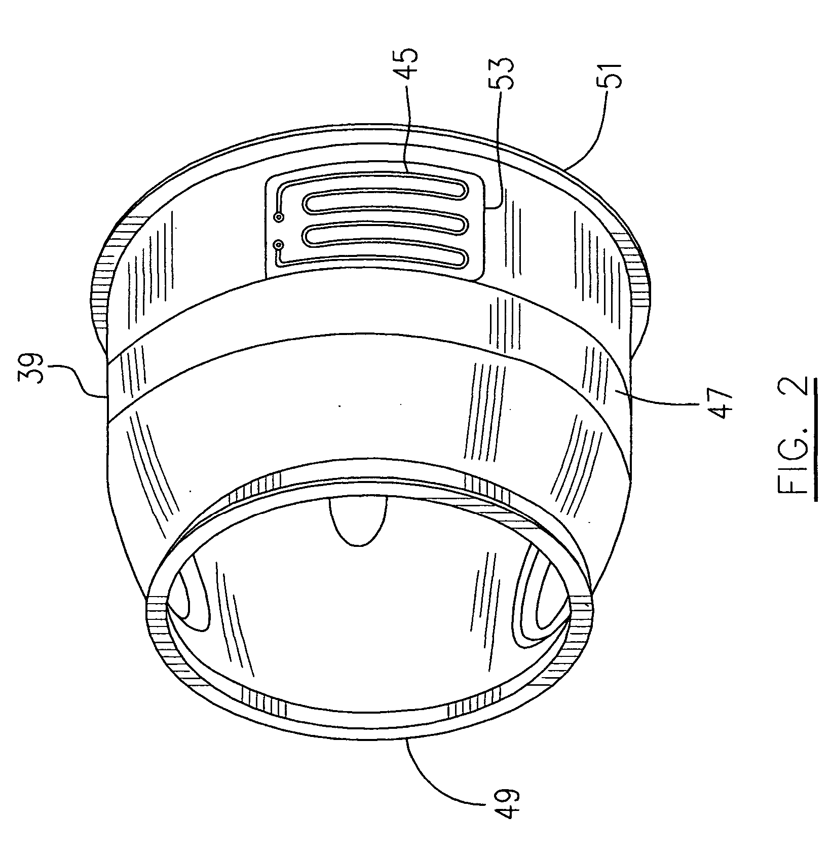
[0016] The engine has a lubricating system (not indicated) including a pump 29 and a heat-exchanger 45 mounted in this embodiment, to the outer bypass duct wall 39. The heat exchanger 45 is connected in fluid communication with the lubricating system of the engine to allow relatively hot oil to flow therethrough and be t...


PUM


Abstract

A method and apparatus for cooling a fluid in a bypass gas turbine engine involves directing the fluid to the bypass duct of the engine to allow for heat exchange from the fluid to bypass air passing through the bypass air duct.

Description

FIELD OF THE INVENTION [0001] The present invention relates to gas turbine engines, and more particularly to a cooling apparatus for cooling of fluid used in a bypass gas turbine engine. BACKGROUND OF THE INVENTION [0002] Lubricating oil used in aircraft gas turbine engines must be cooled. Without proper cooling, poor cooling and / or lubrication of gear and bearings results which may cause problems for engine operation. In addition to employing conventional radiator-type oil coolers, the prior art also describes directing oil through inlet guide vanes or support struts to achieve a cooling benefit from air ingested by the engine. [0003] Nevertheless, there is still a need for improvement of the lubricating oil cooling apparatus for gas turbine engines. SUMMARY OF THE INVENTION [0004] One object of the present invention is to provide a cooling apparatus for cooling of fluid used in a bypass gas turbine engine. [0005] In accordance with one aspect of the present invention, there is a c...

Claims


Application Information

Patent Timeline
Patent Type & Authority Applications(United States)
IPC IPC(8): F02K3/02
CPCF01D25/12F01D25/18F02C7/14Y02T50/675F02K3/06F02K3/115Y02T50/671F02K3/04Y02T50/60
Inventor BRUNO, VITTORIOOLVER, BRYANLOGAN, JOHN ADAM
Owner PRATT & WHITNEY CANADA CORP
Why Eureka
Try Eureka