Eureka AIR delivers breakthrough ideas for toughest innovation challenges, trusted by R&D personnel around the world.

System and method for controlling hydraulic fluid flow

Inactive Publication Date: 2006-03-02
KEJTERPILLAR R L
View PDF16 Cites 20 Cited by
  • Summary
  • Abstract
  • Description
  • Claims
  • Application Information

AI Technical Summary

Benefits of technology

[0006] In one aspect, this disclosure is directed to a method of flowing hydraulic fluid in a work machine. The method includes generating a control signal from an input mechanism and generating a property signal indicative of a viscosity of the hydraulic fluid. The control signal and the property signal are received at a control module. The method also includes determining a desired volume flow rate for the control signal and determining a valve control signal required to achieve the desired volume flow rate for the control signal. The valve control signal is based upon the property signal. The valve control signal is output to a proportional valve to provide the desired volume flow rate through the valve for the command signal.
[0007] In another aspect, this disclosure is direct

Problems solved by technology

When the work machine is started after being idle, the fluid may be cold, and it may take up to an hour for the temperature to rise and stabilize at an operating temperature.
Accordingly, the operator must adjust to the differences in responsiveness of the work machine due to the change in viscosity in the hydraulic fluid, which may cause inefficiencies.
However, the system disclosed in the '323 patent does not control a proportional flow to control a fluid-operated machine component.
Accordingly, the system disclosed in the '323 patent may not provide consistency to a work machine dependent on flow control.

Method used


Image

  • System and method for controlling hydraulic fluid flow
  • System and method for controlling hydraulic fluid flow
  • System and method for controlling hydraulic fluid flow

Examples


Embodiment Construction

[0013] Reference will now be made in detail to exemplary embodiments that are illustrated in the accompanying drawings. Wherever possible, the same reference numbers will be used throughout the drawings to refer to the same or like parts.

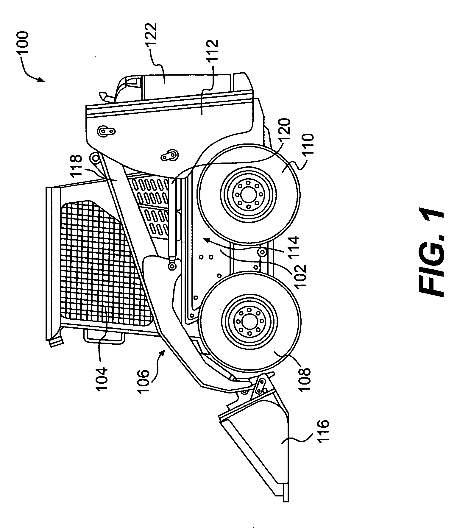
[0014]FIG. 1 shows one exemplary aspect of a work machine 100, shown as a skid steer loader. The work machine 100 includes a body 102, an operator's station 104, an implement assembly 106, and front and rear drive wheels 108, 110, respectively.

[0015] The body 102 may be a frame structure that is connected with and supports the weight of the operator's station 104 and the implement assembly 106. It may include an upright stanchion 112 that connects to the implement assembly 106 and that may be disposed behind the operator's station 104. The operator's station 104 may be an open or an enclosed station that may include a chair and controls for operating various features of the work machine 100.

[0016] The implement assembly 106 may include a lift arm...


PUM


Abstract

A method of flowing hydraulic fluid in a work machine is disclosed. The method includes generating a control signal from an input mechanism and generating a property signal indicative of a viscosity of the hydraulic fluid. The control signal and the property signal are received at a control module. The method also includes determining a desired volume flow rate for the control signal and determining a valve control signal required to achieve the desired volume flow rate for the control signal. The valve control signal is based upon the property signal. The valve control signal is output to a proportional valve to provide the desired volume flow rate through the valve for the command signal.

Description

TECHNICAL FIELD [0001] This disclosure is directed to a system and method for controlling flow of a hydraulic fluid in a work machine. More particularly, this disclosure is directed to a system and method for controlling flow of hydraulic fluid to compensate for viscosity changes of the fluid. BACKGROUND [0002] The properties of hydraulic fluid may be partially dependent on its temperature. For example, when the fluid is cold, it may have a high viscosity, whereas, when the fluid is relatively warmer, the fluid may have a lower viscosity. Work machines, such as skid steer loaders, often use hydraulic fluid to drive actuators and / or hydraulic motors to operate work implements and drive the loader from place to place. For example, a skid steer loader may flow hydraulic fluid through a valve to raise or lower a work implement. When the work machine is started after being idle, the fluid may be cold, and it may take up to an hour for the temperature to rise and stabilize at an operating...

Claims


Application Information

Patent Timeline
IPC IPC(8): F16D33/00F15B21/045
CPCE02F9/2221F15B11/04F15B21/045F15B21/08F15B2211/40515F16D2500/525F15B2211/6343F15B2211/6654F15B2211/6656F16D2500/30803F15B2211/426
Inventor SPORER, MARK ANDREWTHOMAS, DANTE TORANFREBERG, MICHAEL STEVENDVORAK, PAUL ANTHONY
Owner KEJTERPILLAR R L
Why Eureka
Eureka Blog
Learn More