
Method and apparatus for increasing natural convection efficiency in long heat sinks

Inactive Publication Date: 2006-03-02
GELCORE LLC (US)
View PDF13 Cites 26 Cited by
  • Summary
  • Abstract
  • Description
  • Claims
  • Application Information

AI Technical Summary

Problems solved by technology

The diverter disrupts laminar vertical airflow over the heat dissipation surface.

Method used


Image

  • Method and apparatus for increasing natural convection efficiency in long heat sinks
  • Method and apparatus for increasing natural convection efficiency in long heat sinks
  • Method and apparatus for increasing natural convection efficiency in long heat sinks

Examples


Embodiment Construction

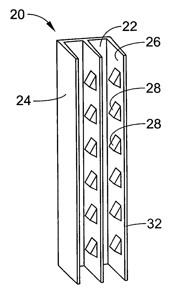
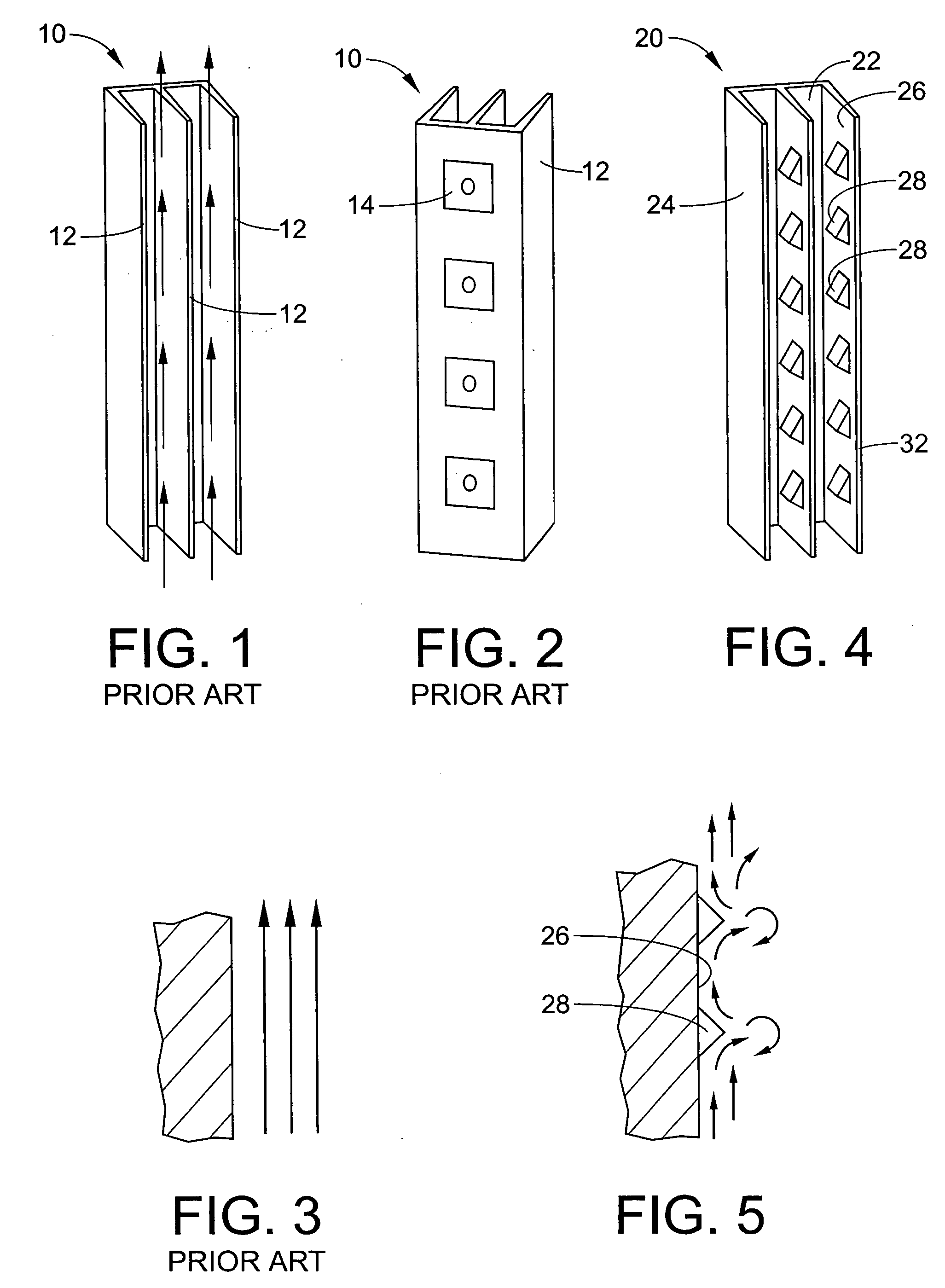
[0020] With reference to FIG. 4, a heat sink 20 for cooling electrical components, for example LEDs, (not shown but similar to components 14 in FIG. 2) is provided. The heat sink 20 generally includes a base 22 having a plurality of fins 24 extending from the base. Electrical components can mount to the base on a mounting surface (not shown) that is opposite the fins 24. Alternatively, the electrical components can mount to other surfaces that are in thermal communication with a heat dissipation surface 26. In this embodiment, the fins 24 along with the rear side of the base 22 provide the heat dissipation surface 26 over which air flows to remove heat from the heat sink 20.

[0021] In this particular embodiment, a long, vertically oriented heat sink 22 is provided to generate upward laminar flow via natural convection. Although not to be bound by theory, computer modeling has indicated that a long heat sink, i.e. a heat sink where the vertical dimension is about ten times the remain...


PUM


Abstract

An electrical apparatus that is cooled via natural convection includes an electrical component, a vertical heat dissipation surface in thermal communication with the electrical component, and a diverter extending from the heat dissipation surface. The diverter disrupts vertical airflow over the heat dissipation surface.

Description

BACKGROUND OF THE INVENTION [0001] Heat sinks are used to cool electrical devices, such as chips, diodes, and the like. Air, or some other fluid, flows over heat dissipation surfaces of the heat sink to cool the heat sink, and thus the electrical device. The heat transfer is mainly by way of convection. [0002] Generally, natural convection is the cooling of a vertical hot surface in a large quiescent body of air. Lower-density air next to the vertical hot surface moves upward because of the buoyant force of higher-density cooler air farther away from the vertical surface. Movement of the air adjacent the vertical surface increases in velocity from zero at the vertical surface to a maximum velocity at a distance from the vertical surface and then decreases back to a velocity of zero as ambient surrounding conditions are reached. The temperature of the moving air decreases from the heated surface temperature to the ambient air temperature. As the temperature of the moving air approach...

Claims


Application Information

Patent Timeline
IPC IPC(8): F25D23/00G06F1/20H05K5/00H05K7/20
CPCG06F1/20H01L23/367H01L23/467H01L2924/0002H01L2924/00
Inventor PETROSKI, JAMES T.
Owner GELCORE LLC (US)
Features
  • Generate Ideas
  • Intellectual Property
  • Life Sciences
  • Materials
  • Tech Scout
  • Unparalleled Data Quality
  • Higher Quality Content
  • 60% Fewer Hallucinations
Learn More