Deburring device, and deburring method for punch press, and punch press

a deburring device and punch press technology, applied in the direction of burnishing machines, metal-working equipment, manufacturing tools, etc., can solve the problems of not producing a deburring effect on a thicker plate material, affecting the delivery of machined products, and increasing costs, so as to achieve continuous and smooth removal of burrs

Active Publication Date: 2006-03-02
MURATA MASCH LTD
View PDF5 Cites 24 Cited by
  • Summary
  • Abstract
  • Description
  • Claims
  • Application Information

AI Technical Summary

Benefits of technology

[0021] The present invention provides another deburring device used for a punch press, the device having the upper tool and lower tool arranged opposite each other, the upper and lower tools each having the ball holding member and the ball rotatably supported by the ball holding member and projecting from the surface of the ball holding member toward the opposite surface of the opposite ball holding member. The plate material moves while being sandwiched between the upper and lower balls to continuously remove the burrs produced along the cut portion formed on the plate material. It is thus possible to continuously and smoothly remove the burrs produced in the cut portion formed by, for example, continuous machining with the punch press so that the removal is carried out as a process with the same punch press.

Problems solved by technology

The need for the deburring step is a factor delaying the delivery of machined products and increasing costs.
However, this method is effective on a thin plate material but does not produce a deburring effect on a thicker plate material.
However, this method is effective on a round punch hole but cannot carry out deburring on a slot.

Method used


Image

  • Deburring device, and deburring method for punch press, and punch press
  • Deburring device, and deburring method for punch press, and punch press
  • Deburring device, and deburring method for punch press, and punch press

Examples


Embodiment Construction

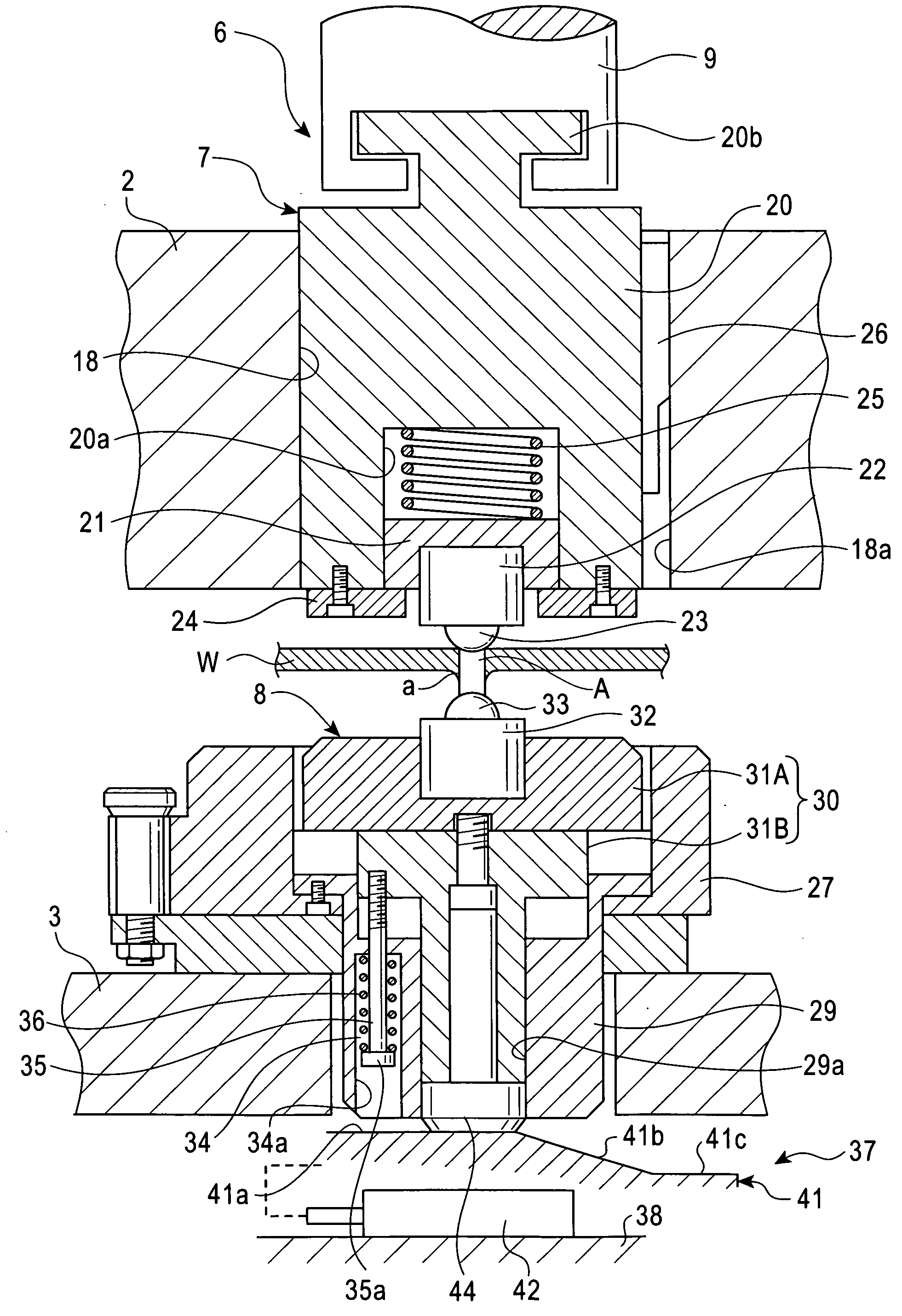
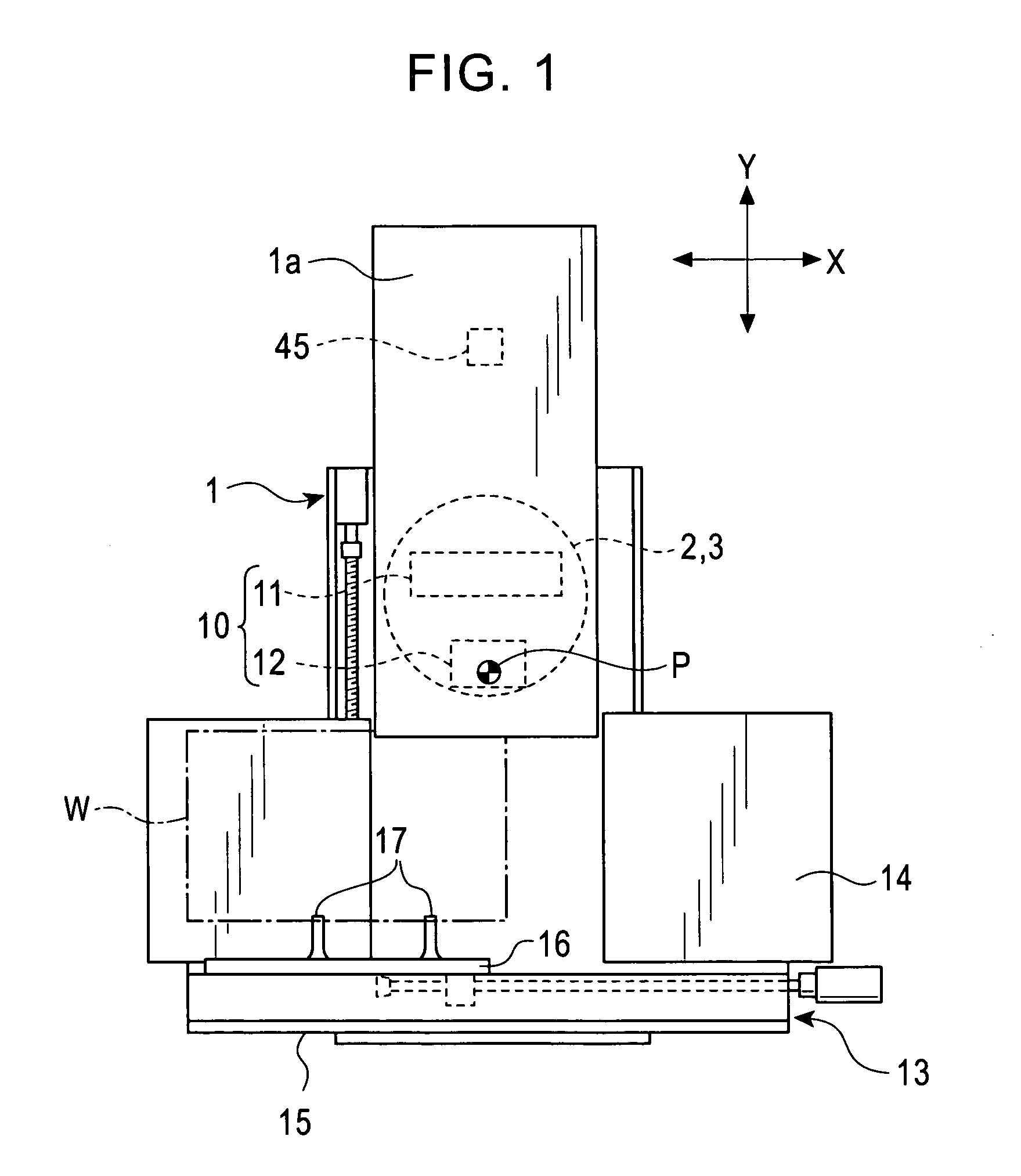
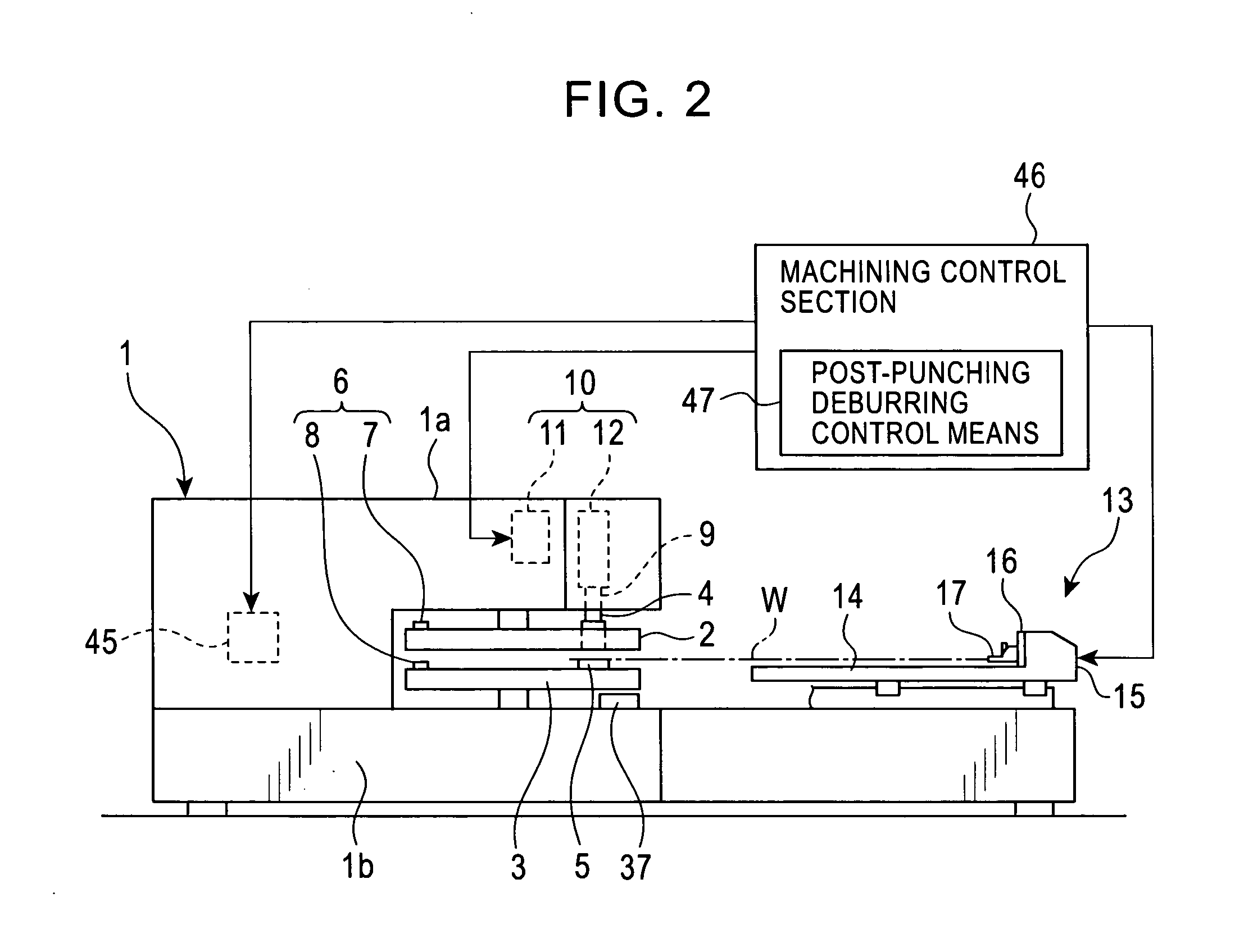
[0033] A first embodiment of the present invention will be described with reference to FIGS. 1 to 8. FIG. 1 is a plan view schematically showing the configuration of a punch press comprising a deburring device according to the embodiment. FIG. 2 is a side view of this configuration.

[0034] In the punch press, an upper and lower turrets 2, 3 serving as tool supports are supported on an upper frame portion 1a and lower frame portion 1b of a frame 1 so that the turrets 2, 3 can rotate around a concentric vertical axis. The following components are arranged on the upper and lower turrets 2, 3 in a circumferential direction: a plurality of punch tools 4 and die tools 5, and an upper tool 7 and a lower tool 8 of a deburring device 6. The upper and lower tools 7, 8 of the deburring device 6 may be provided in only one area or several types of upper and lower tools 7, 8 may be provided in a plurality of areas. Each punch tool 4 and the upper tool 7 of the deburring device 6 are indexed to a...


PUM

PropertyMeasurementUnit
diameteraaaaaaaaaa
widthaaaaaaaaaa
pressureaaaaaaaaaa

Abstract

The present invention provides a deburring device for a punch press which can remove burrs produced along a slot or a cut portion formed in a plate material by punching or cutting using a punch press so that the removal is carried out as a process with the same punch press. A deburring device 6 for a punch press has an upper tool 7 and a lower tool 8 arranged opposite each other. The upper and lower tools 7, 8 each have a ball holding member 22, 32, respectively, and a ball 23, 33, respectively, rotatably supported by the ball holding member and projecting from a surface of the ball holding member 22, 32 toward an opposite surface of the opposite ball holding member 32, 22. Each of the upper and lower balls 23, 33 has a diameter larger than the width of the slot A, in its portion projecting from the ball holding member 22, 32, respectively, the slot A being formed in the plate material W so as to extend across the plane. The plate material W moves with the vertical pair of balls 23, 33 partly fitted into the slot A and with the plate material W sandwiched between the upper and lower balls 23, 33 to continuously remove burrs (a) produced along a longitudinal direction of the slot A. The deburring device 6 continuously removes not only the burrs produced along the slot A but also those produced along a cut portion in the plate material W as described above.

Description

FIELD OF THE INVENTION [0001] The present invention relates to a deburring device and a deburring method for a punch press which removes burrs produced on a plate material as a result punching with a punch press, as well as the punch press. BACKGROUND OF THE INVENTION [0002] When a plate material is punched using a punch press, burrs are always produced on the back surface of a punched portion of the plate material owing to a die clearance. To remove the burrs produced on the back surface of the plate material, the conventional art requires manual sanding of the plate material during a post-process or execution of a deburring step using a deburring machine. The need for the deburring step is a factor delaying the delivery of machined products and increasing costs. [0003] The techniques described below have been proposed which carry out deburring using a punch press instead of the deburring executed during the post-process. One of the techniques involves providing a polishing member ...

Claims


Application Information

Patent Timeline
Patent Type & Authority Applications(United States)
IPC IPC(8): B21D28/00
CPCB21D19/00Y10T29/47B21D28/12
Inventor NISHIBU, HIDEHISA
Owner MURATA MASCH LTD
Why Eureka
Try Eureka