Method of producing nozzle plate and said nozzle plate

a technology of nozzle plate and nozzle plate, which is applied in the field of producing nozzle plate and said nozzle plate, can solve the problems of reducing affecting the quality of ink ejection, so as to achieve the effect of improving the impact accuracy of ink ejection from the ink ejection por

Active Publication Date: 2005-05-26
BROTHER KOGYO KK
View PDF14 Cites 9 Cited by
  • Summary
  • Abstract
  • Description
  • Claims
  • Application Information

AI Technical Summary

Benefits of technology

[0014] According to one embodiment of the invention, a nozzle plate includes a nozzle surface defining an ink ejection port; and a nozzle hole. The nozzle hole includes a taper hole portion and a curved-surface hole portion. The taper hole portion has an inner surface of a truncated conical shape and has the smallest diameter at one end thereof. The curved-surface hole portion has a

Problems solved by technology

Such a synthetic resin has a large coefficient of linear expansion, and hence there arises a problem in that, when the substrate is heated during a production process, positional displacement is caused by thermal expansion.
When a meniscus is formed in the vicinity of the connection end between the curved-

Method used


Image

  • Method of producing nozzle plate and said nozzle plate
  • Method of producing nozzle plate and said nozzle plate
  • Method of producing nozzle plate and said nozzle plate

Examples


Embodiment Construction

[0034] An embodiment of the invention will be described with reference to the accompanying drawings. In the embodiment, the invention is applied to a nozzle plate for an ink jet head which ejects ink onto a sheet.

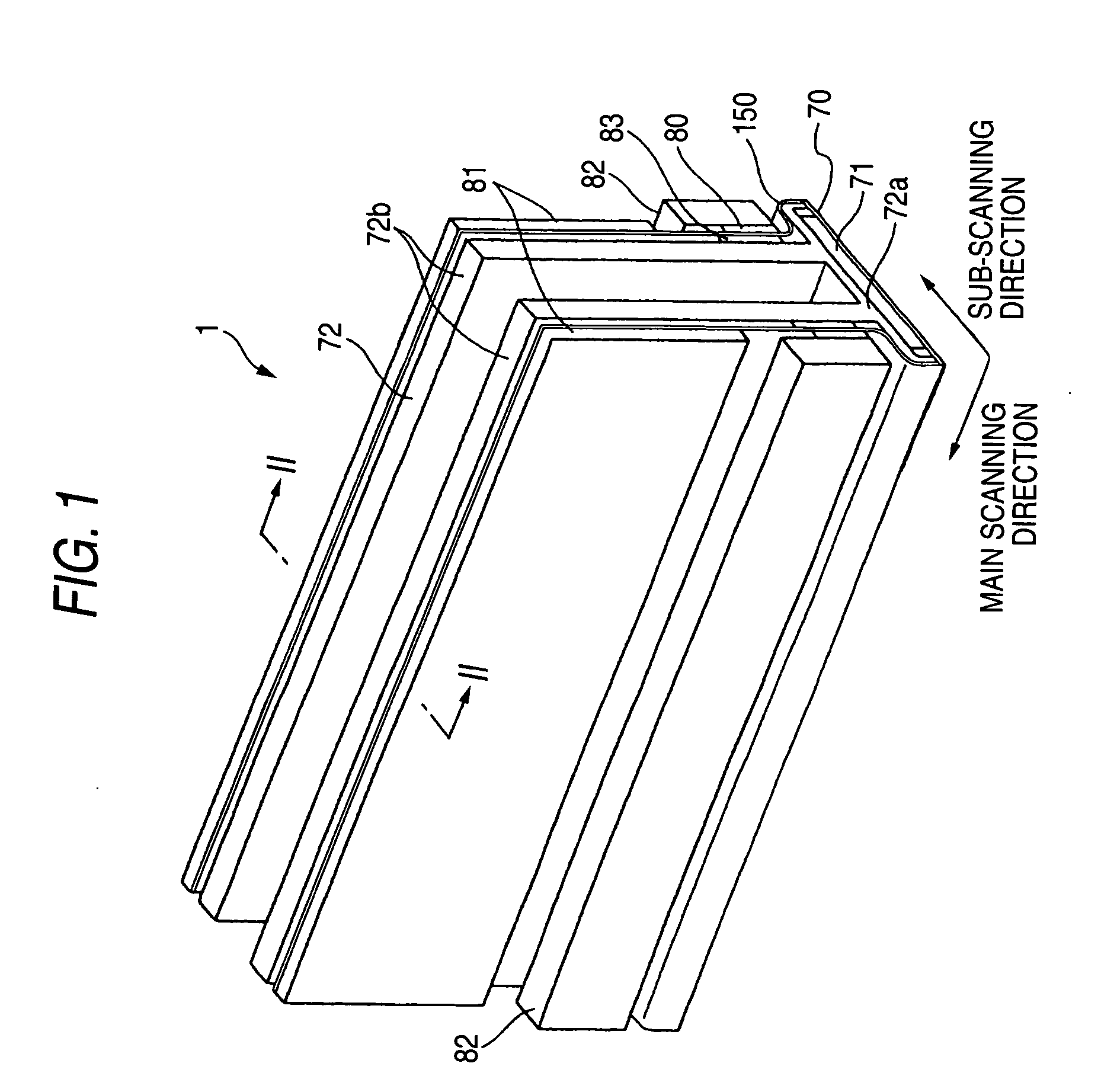
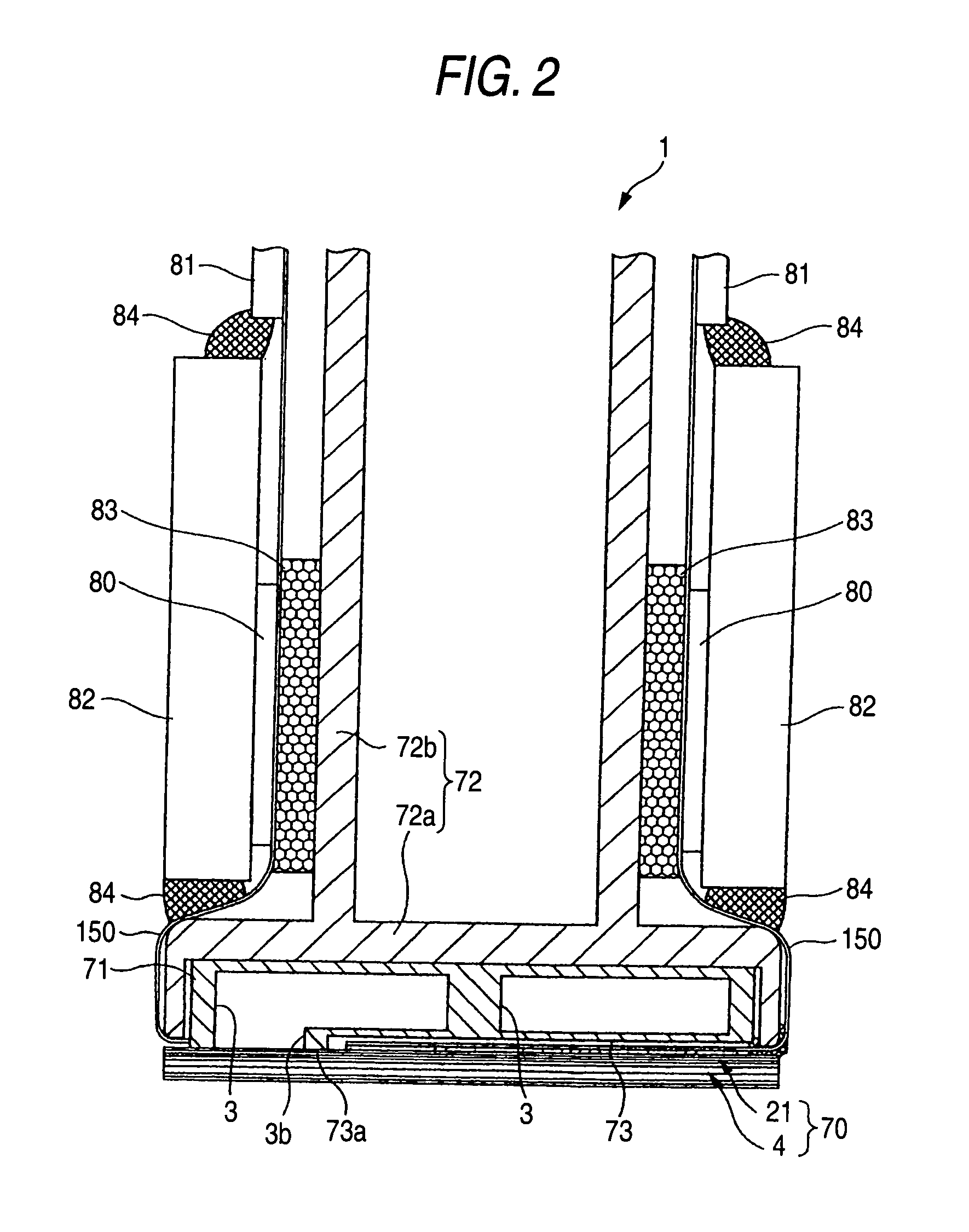
[0035] First, the ink jet head will be described. As shown in FIGS. 1 and 2, the ink jet head 1 in the embodiment includes: a head body 70 having a rectangular planar shape extending in the in a main scanning direction along which an ink is ejected to a sheet; and a base block 71 which is placed above the head body 70, and in which two ink reservoirs 3 serving as flow paths of an ink to be supplied to the head body 70 are formed.

[0036] The head body 70 includes: a flow path unit 4 in which ink flow paths are formed; and a plurality of actuator units 21 which are bonded to the upper face of the flow path unit 4. The flow path unit 4 and the actuator units 21 are configured by laminating and bonding plural thin plates together. Flexible printed circuits (FPCs) 150 which fun...


PUM

PropertyMeasurementUnit
Diameteraaaaaaaaaa
Shapeaaaaaaaaaa
Orderaaaaaaaaaa

Abstract

A nozzle plate includes a nozzle surface and a nozzle hole. The nozzle surface defines an ink ejection port. The nozzle hole includes a taper hole portion and a curved-surface hole portion. The taper hole portion has an inner surface of a truncated conical shape and has the smallest diameter at one end thereof. The curved-surface hole portion has an inner surface of a curved-surface shape. The inner diameter of the curved-surface hole portion gradually decreases as approaching from the one end of the taper hole portion to the ink ejection port.

Description

BACKGROUND OF THE INVENTION [0001] 1. Field of the Invention [0002] The present invention relates to a method of producing a nozzle plate including nozzle holes for ejecting an ink, and also to such a nozzle plate. [0003] 2. Description of the Related Art [0004] An ink jet head includes a nozzle plate having many nozzle holes, and is configured so that an ink is ejected from the many nozzle holes onto a recording medium. An example of such a nozzle plate is a nozzle plate 100 in which, as shown in FIG. 16, a nozzle hole 102 having an inner face of a tapered shape is formed in a substrate 101 made of polyimide or the like by excimer laser processing or another method. [0005] In another nozzle plate 110, as shown in FIG. 17, a nozzle hole 112 is formed in a metal substrate 111 by press working using a punch or the like. The nozzle hole is formed of: a tapered hole portion 112a which is continuous to an ink flow path on an upstream side, and which has a truncated conical shape; and a c...

Claims


Application Information

Patent Timeline
IPC IPC(8): B41J2/135B05C5/00B41J2/14B41J2/16
CPCB41J2/1433B41J2/162B41J2/1632B41J2/1637B41J2002/14217B41J2002/14225Y10T29/49789B41J2002/14459Y10T29/49798Y10T29/49812Y10T29/49401Y10T29/49833B41J2002/14306
Inventor ITO, ATSUSHIOKAWA, YASUO
Owner BROTHER KOGYO KK
Why Eureka
Try Eureka