
Wheel deburring device

a deburring device and wheel technology, applied in the direction of flexible wheel, edge grinding machine, manufacturing tools, etc., can solve the problems of unsatisfactory rims and low linear velocity of a central position of a large-disc brush, and achieve high degree of automation, high universality, and safe

Active Publication Date: 2018-10-30
CITIC DICASTAL
View PDF6 Cites 9 Cited by
  • Summary
  • Abstract
  • Description
  • Claims
  • Application Information

AI Technical Summary

Benefits of technology

The present invention is a device for removing burrs from the front surface and back cavity of a wheel. The device has several advantages: it can remove burrs from both surfaces, the inner and outer rings of the lower brush rotate separately, and round brushes can auto-rotate. Furthermore, it can also remove burrs from the roots of flanges and rims of wheels. The device is advanced technology, highly automated, and safe and stable to perform its duties.

Problems solved by technology

In the traditional burr brushing mode, the linear velocity of a central position of a large-disc brush is relatively low, and thus the treatment on corner burrs of roots of flanges and corner burrs of roots of rims is not ideal, so that a novel deburring device is urgently required to excellently remove the corner burrs of the roots of the flanges and the corner burrs of the roots of the rims.

Method used


Image

  • Wheel deburring device
  • Wheel deburring device
  • Wheel deburring device

Examples


Embodiment Construction

[0015]In the following, the details and working conditions of a specific device provided by the present invention are described in combination with the figures.

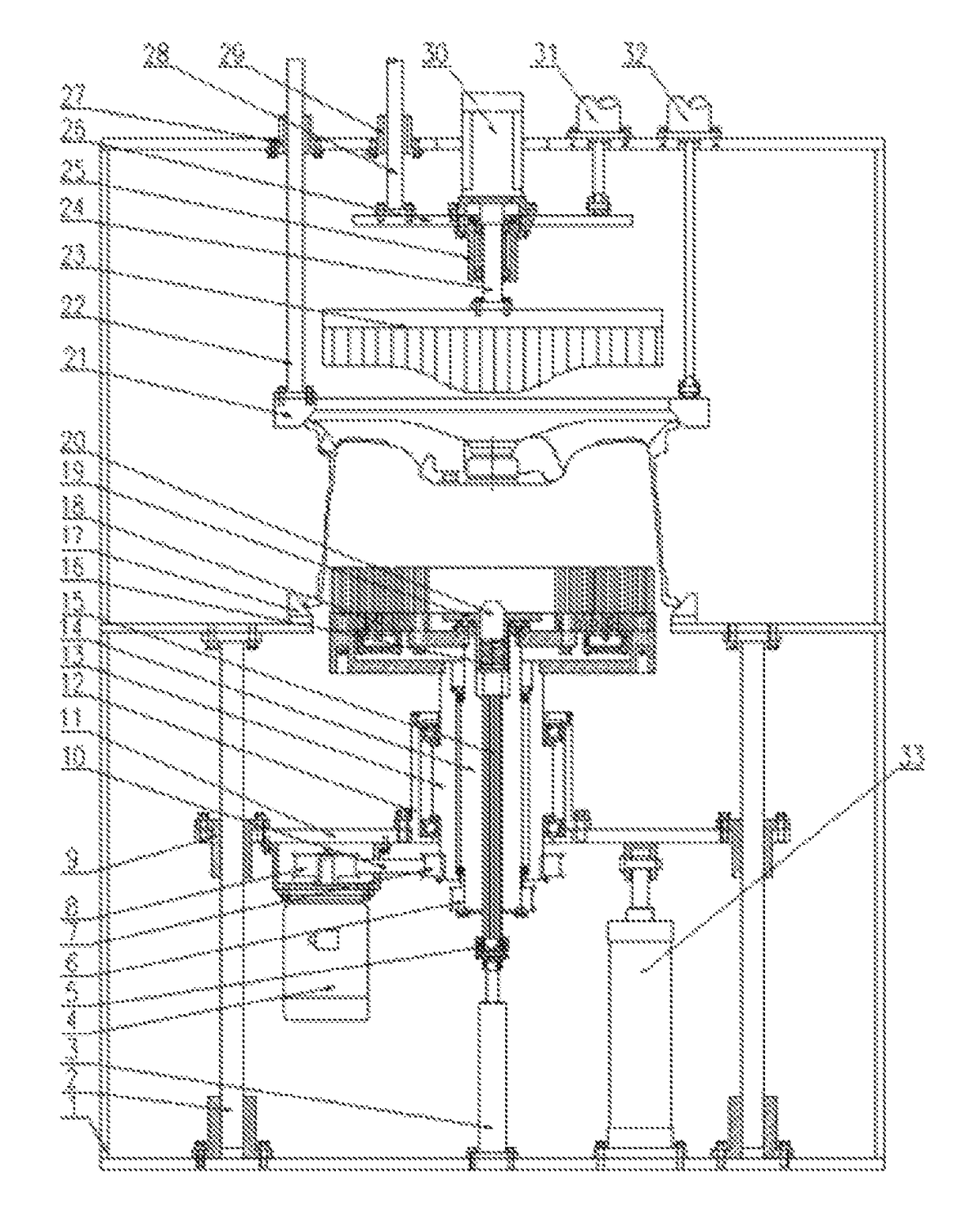
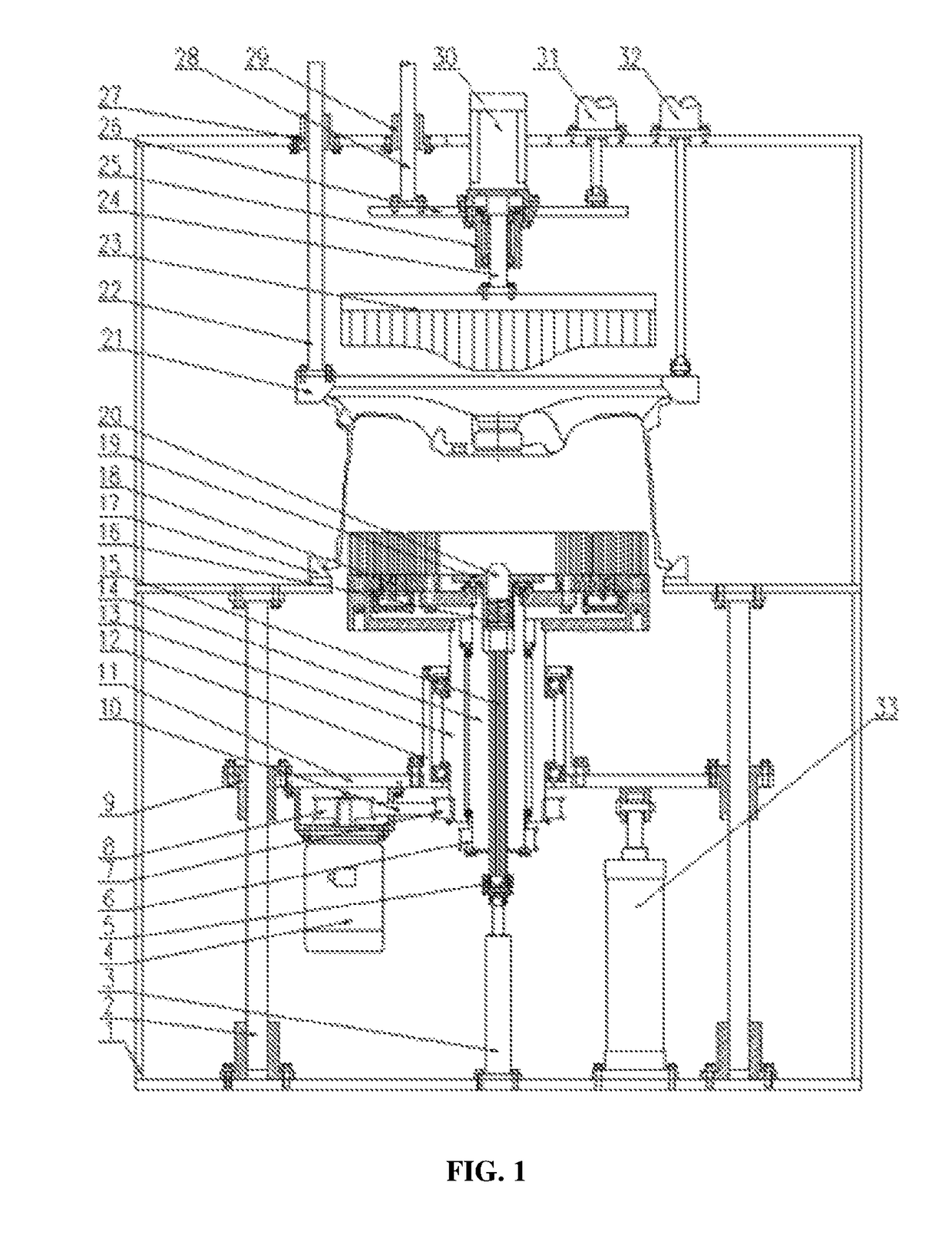
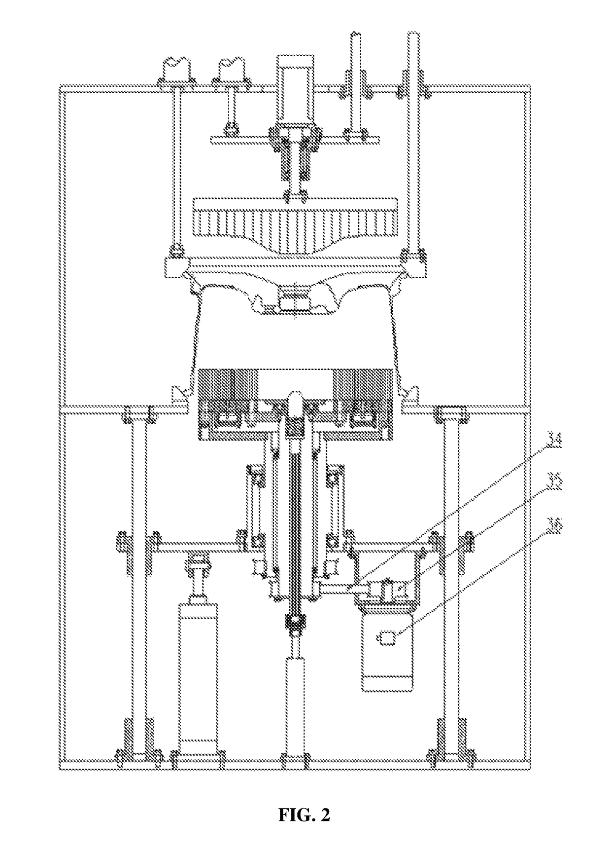
[0016]An improved wheel deburring device is composed of a machine frame 1, first guide posts 2, a first cylinder 3, a first motor 4, a rotary joint 5, a first belt pulley 6, a second belt pulley 7, a third belt pulley 8, first guide sleeves 9, a first synchronizing belt 10, a first rising and falling plate 11, a large bearing block 12, a hollow shaft 13, a spline housing 14, a spline shaft 15, a spring 16, a clamp 17, a lower brush 18, a flange sleeve 19, a conical column 20, a pressing ring 21, second guide posts 22, an upper brush 23, a rotary shaft 24, an upper bearing block 25, a second rising and falling plate 26, second guide sleeves 27, third guide posts 28, third guide sleeves 29, a second motor 30, second cylinders 31, third cylinders 32, fourth cylinders 33, a second synchronizing belt 34, a fourth belt pulley 35 an...


PUM


Abstract

A wheel deburring device. A second motor drives an upper brush to rotate, second cylinders enable the upper brush to fall through third posts, and burrs of a front surface can be removed when the upper brush is in contact with the front surface of a wheel; a first motor enables an outer ring and a first geared ring to rotate through a first belt; a third motor enables an inner ring and a second geared ring to rotate through a second belt, directions of rotation of the inner ring and the second geared ring are opposite to that of the outer ring, and brushes are driven to rotate through a gear; and fourth cylinders enable a lower brush to rise through first guide posts, and burrs of a back cavity of the wheel can be removed when the lower brush is in contact with that back cavity.

Description

TECHNICAL FIELD[0001]The present invention relates to a deburring device, and in particular to a wheel deburring device, of which an outer ring and an inner ring of a lower brush rotate separately and round brushes can autorotate.BACKGROUND ART[0002]A deburring procedure is an indispensable procedure of a wheel production process, and the deburring effect will directly affect the painting effect of a follow-up procedure. In the traditional burr brushing mode, the linear velocity of a central position of a large-disc brush is relatively low, and thus the treatment on corner burrs of roots of flanges and corner burrs of roots of rims is not ideal, so that a novel deburring device is urgently required to excellently remove the corner burrs of the roots of the flanges and the corner burrs of the roots of the rims.SUMMARY OF THE INVENTION[0003]An object of the present invention is to provide a wheel deburring device, which has the advantages that burrs of a front surface and a back cavit...

Claims


Application Information

Patent Timeline
Patent Type & Authority Patents(United States)
IPC IPC(8): B24B29/00B24D13/14B24B5/40B24B9/04B24B29/04B24B27/00B24B5/44B24B41/06B24B5/08
CPCB24B29/005B24B5/08B24B5/40B24B5/44B24D13/145B24B27/0076B24B29/04B24B41/06B24B9/04
Inventor XUE, BOWENGUO, JIANDONG
Owner CITIC DICASTAL
Learn More