Ultrasonic diagnosing device

Inactive Publication Date: 2006-03-02
PANASONIC CORP
View PDF9 Cites 9 Cited by
  • Summary
  • Abstract
  • Description
  • Claims
  • Application Information

AI Technical Summary

Benefits of technology

[0012] The present invention has a first object to provide an ultrasonic diagnostic apparatus that can solve those problems and can carry out an observation by positioning to a straight organ such as a blood vessel and the like without any skilled technique and can obtain motion information of a high precision.
[0013] Also, the present invention has a second object to provide an ultrasonic diagnostic apparatus that can position a probe to a position of an inspection sample accurately at an excellent reproducibility.
[0020] In the foregoing ultrasonic diagnostic apparatus, the probe has the plurality of transducer element arrays, and the plurality of fault images are displayed correspondingly to the respective transducer element arrays. Thus, since the positions of the probe and the inspection sample can be checked from a plurality of different directions, the position of the probe can be aligned with the position of the inspection sample easily and surely at the excellent reproducibility.
[0021] In the foregoing ultrasonic diagnostic apparatus, preferably, the image display displays a guide line that indicates positions of the first transducer element array and the second transducer element array, together with a fault image of an inspection sample. According to this preferred example, since the position of the probe can be easily checked on the fault image, the positioning of the probe can be executed further easily.
[0022] Also, in the foregoing ultrasonic diagnostic apparatus, preferably, the first transducer element array and the second transducer element array are arranged so as not to overlap with each other. The intersection between the first transducer element array and the second transducer element array requires the change in the shape of the transducer element array, such as the narrower widths of the mutual transducer elements in the intersection portion and the like. However, such a change may drop a reception sensitivity of the ultrasonic wave. However, according to this preferred example, such a problem can be avoided.

Problems solved by technology

However, the foregoing ultrasonic diagnostic apparatus has a problem that the alignment of the probe is difficult in measuring.
This is a problem that is similarly induced in inspection samples except the atheroma (for example, a tumor inside a liver, a polyp inside a gallbladder and the like).
In the conventional example, for example, when the blood vessel is observed as the straight organ, a problem that it is difficult to align the array direction of the ultrasonic probe 112 with the direction of the blood vessel is induced.
However, this requires a skilled technique.

Method used


Image

  • Ultrasonic diagnosing device
  • Ultrasonic diagnosing device
  • Ultrasonic diagnosing device

Examples


first embodiment

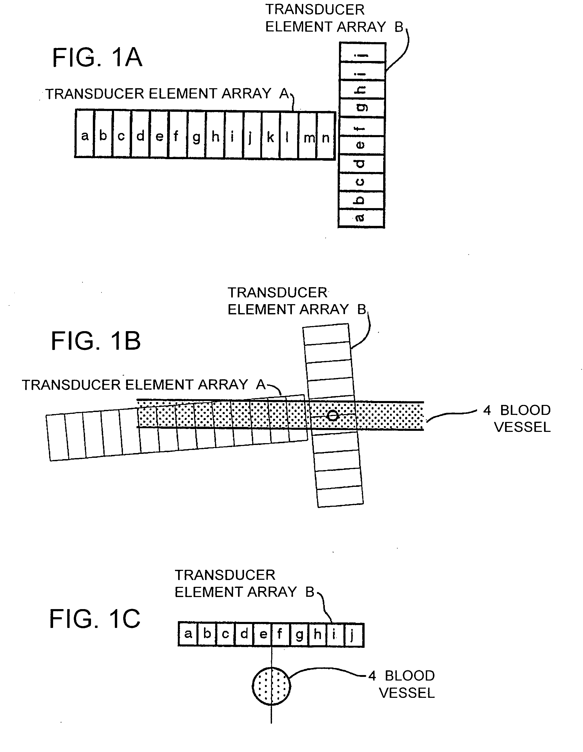
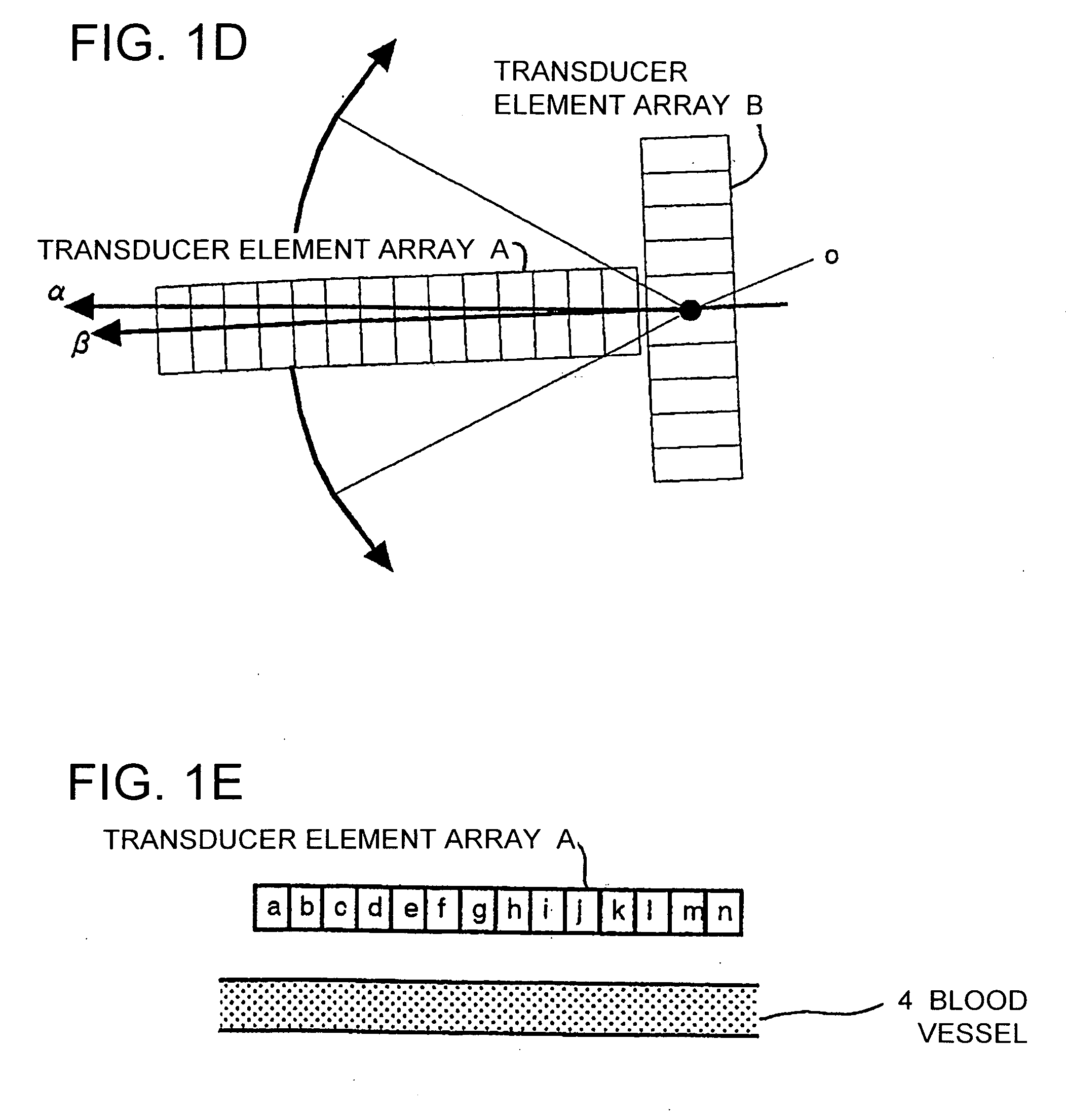
[0061]FIGS. 1A to 1E are explanation views when inspection regions of a plurality of transducer element arrays in the first embodiment of the present invention are positioned to a blood vessel. FIG. 1A is a top view showing the arrangement directions of two transducer element arrays A, B. The transducer element array A is configured such that transducer elements a to n are straightly arrayed, and the transducer element array B is configured such that transducer elements a to j are straightly arrayed. The transducer element array A and the transducer element array B are arranged in a T-shaped type with respect to an inspection sample, and the center of the transducer element array B is located on an extension of a central line (not shown) penetrating the centers of the transducer elements a to n of the transducer element array A.

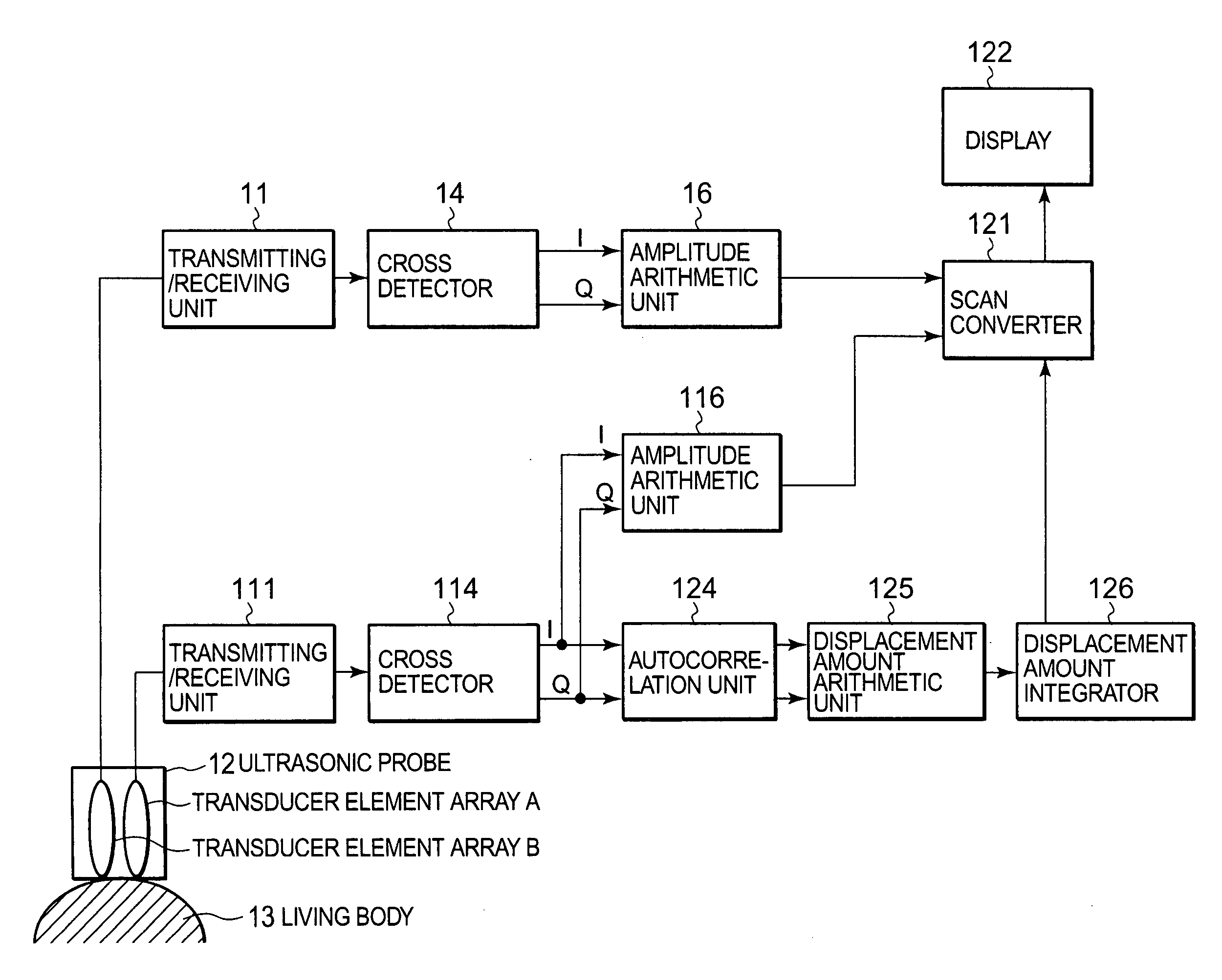
[0062]FIG. 2 shows an example of a block diagram of an ultrasonic diagnostic apparatus connected to the two transducer element arrays A, B. FIG. 2 differs f...

second embodiment

[0069]FIGS. 4A to 4E are explanation views when inspection regions of a plurality of transducer element arrays in the second embodiment of the present invention are positioned to the blood vessel. FIG. 4A is a top view showing the arrangements of the two transducer element arrays A, B. Similarly to the first embodiment, the transducer element array A is provided with individual transducer elements a to r, and the transducer element array B is provided with individual transducer elements a to j. The transducer element array A and the transducer element array B are arranged in a cross-shaped type, as shown in FIG. 4A. A central line (not shown) penetrating the centers of the transducer elements a to r of the transducer element array A and a central line (not shown) penetrating the centers of the transducer elements a to j of the transducer element array B intersect squarely.

[0070] Even in the second embodiment of the present invention, FIG. 4B and FIG. 4C show the top view and the ri...

third embodiment

[0071]FIGS. 5A to 5F are explanation views when inspection regions of a plurality of transducer element arrays in the third embodiment of the present invention are positioned to the blood vessel. This embodiment uses three transducer element arrays A, B and C. FIG. 5A is a top view showing the arrangements of the three transducer element arrays A, B and C. The transducer element array A is provided with individual transducer elements a to j, and the transducer element arrays B, C are provided with individual transducer elements a to j, respectively. The transducer element array A, the transducer element array B and the transducer element array C are arranged in an H-shaped type, as shown in FIG. 5A. An extension of a central line (not shown) penetrating the centers of the transducer elements a to j of the transducer element array A is located at the centers of the transducer element array B and the transducer element array C.

[0072] The ultrasonic diagnostic apparatus connected to t...


PUM


Abstract

An ultrasonic diagnostic apparatus that can execute the positioning of a probe and an inspection sample easily and accurately at an excellent reproducibility is disclosed. This is the ultrasonic diagnostic apparatus that includes; a probe for transmitting an ultrasonic wave into a living body and receives a reflection wave from an inspection sample inside the living body; an image generator for generating a fault image of the inspection sample in accordance with a signal received by the probe; and an image display for displaying the fault image. The probe has a first transducer element array 1 and a second transducer element array 2, and these transducer element arrays are arranged such that array directions intersect each other. Moreover, the image generator and the image display generate and display a first fault image corresponding to a signal received by the first transducer element array and a second fault image corresponding to a signal received by the second transducer element array.

Description

TECHNICAL FIELD [0001] The present invention relates to an ultrasonic diagnostic apparatus for performing an ultrasonic transmission / reception through a transducer element array and obtaining information of a body. [0002] The present invention relates to an ultrasonic diagnostic apparatus for obtaining information of a straight organ, for example, such as a blood vessel. BACKGROUND ART [0003] An ultrasonic diagnostic apparatus performs an ultrasonic transmission / reception on a living body and consequently obtains two-dimensional information inside the living body, and this is used in various medical fields. Such an ultrasonic diagnostic apparatus, there are known: a B-mode displaying apparatus for using amplitude information and obtaining a fault image of an inspection sample; a Doppler blood flow meter for using a fact that a phase of a reflection wave of moving blood is changed with aged deterioration; and a color flow blood flow image apparatus; and the like. Also, in recent year...

Claims


Application Information

Patent Timeline
IPC IPC(8): G01N29/06G01N29/26A61B8/14A61B8/06
CPCA61B5/02007A61B8/06A61B8/463A61B8/145A61B8/14A61B8/4494
Inventor SATO, TOSHIHARUHAGIWARA, HISASHITANNAKA, YOSHINAO
Owner PANASONIC CORP
Why Eureka
Try Eureka