PV laminate backplane with optical concentrator

Inactive Publication Date: 2006-03-02
GENERAL ELECTRIC CO
View PDF12 Cites 54 Cited by
  • Summary
  • Abstract
  • Description
  • Claims
  • Application Information

AI Technical Summary

Benefits of technology

[0006] In an exemplary embodiment, a photovoltaic (PV) laminate backplane assembly includes an insulative substrate and a metal foil bonded to the insulative substrate on a first surface and is electrically receptive for mounting a solar cell on a second surface opposite the first surface. The metal foil includes a light concentrator disposed at exposed regions on the second surface of the metal foil and is configured to reflect incident light thereon to the solar cell to increase a concentration of light on the solar cell in a range of about 1.5× to about 4×.
[0007] In another exemplary embodiment, a solar cell laminate assembly includes a plurality of solar cells each having a first side and a second side, each of the plurality of solar cells is confi

Problems solved by technology

Providing electricity through photovoltaic (PV) cells is becoming more popular as this technology has decreased in cost and reliance on other sources of electric power is increasingly disfavored for environmental and strategic reasons.
However, providing a cost effective PV module has been elusive since the cost of the PV module i

Method used


Image

  • PV laminate backplane with optical concentrator
  • PV laminate backplane with optical concentrator
  • PV laminate backplane with optical concentrator

Examples


Example

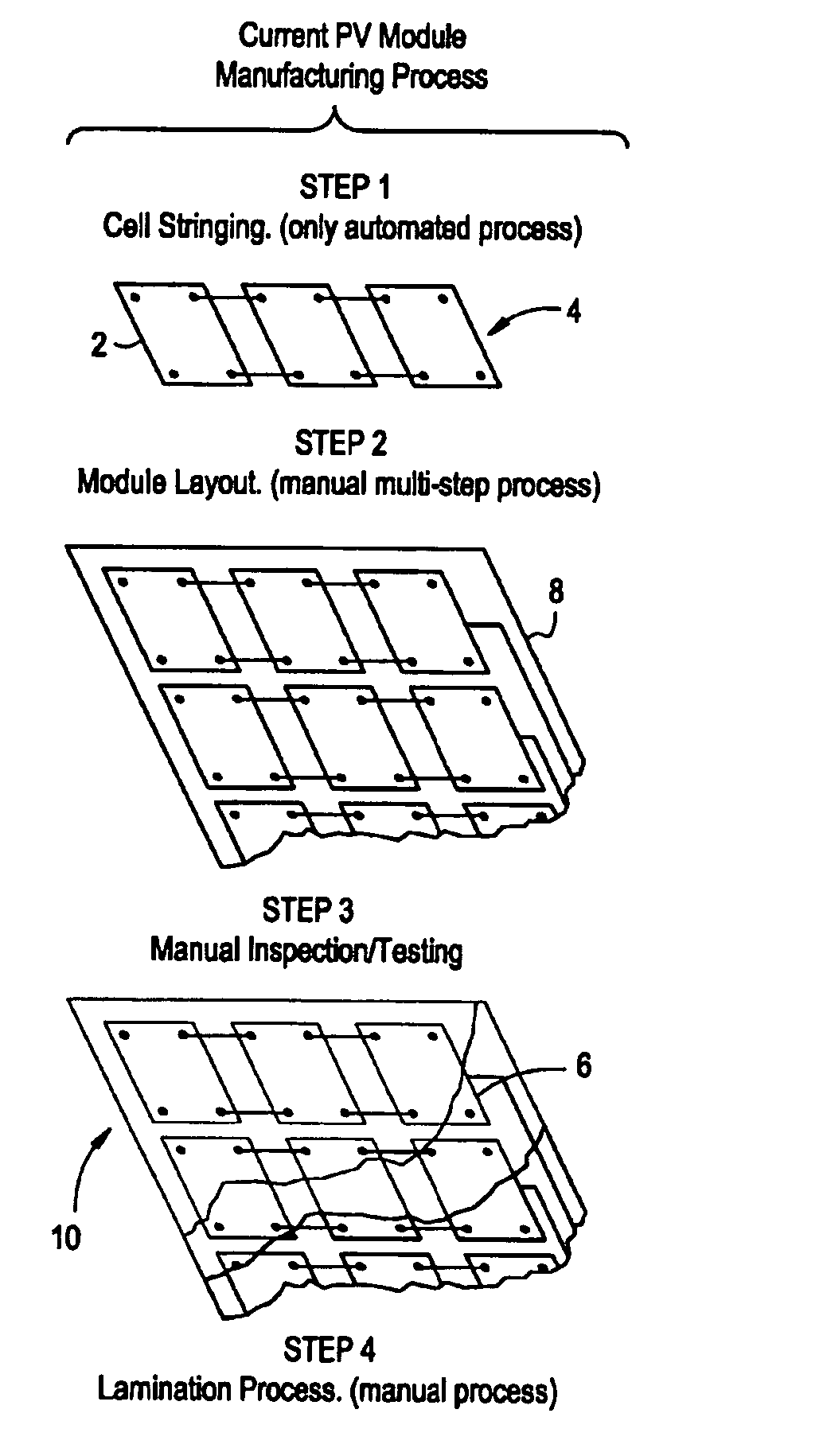
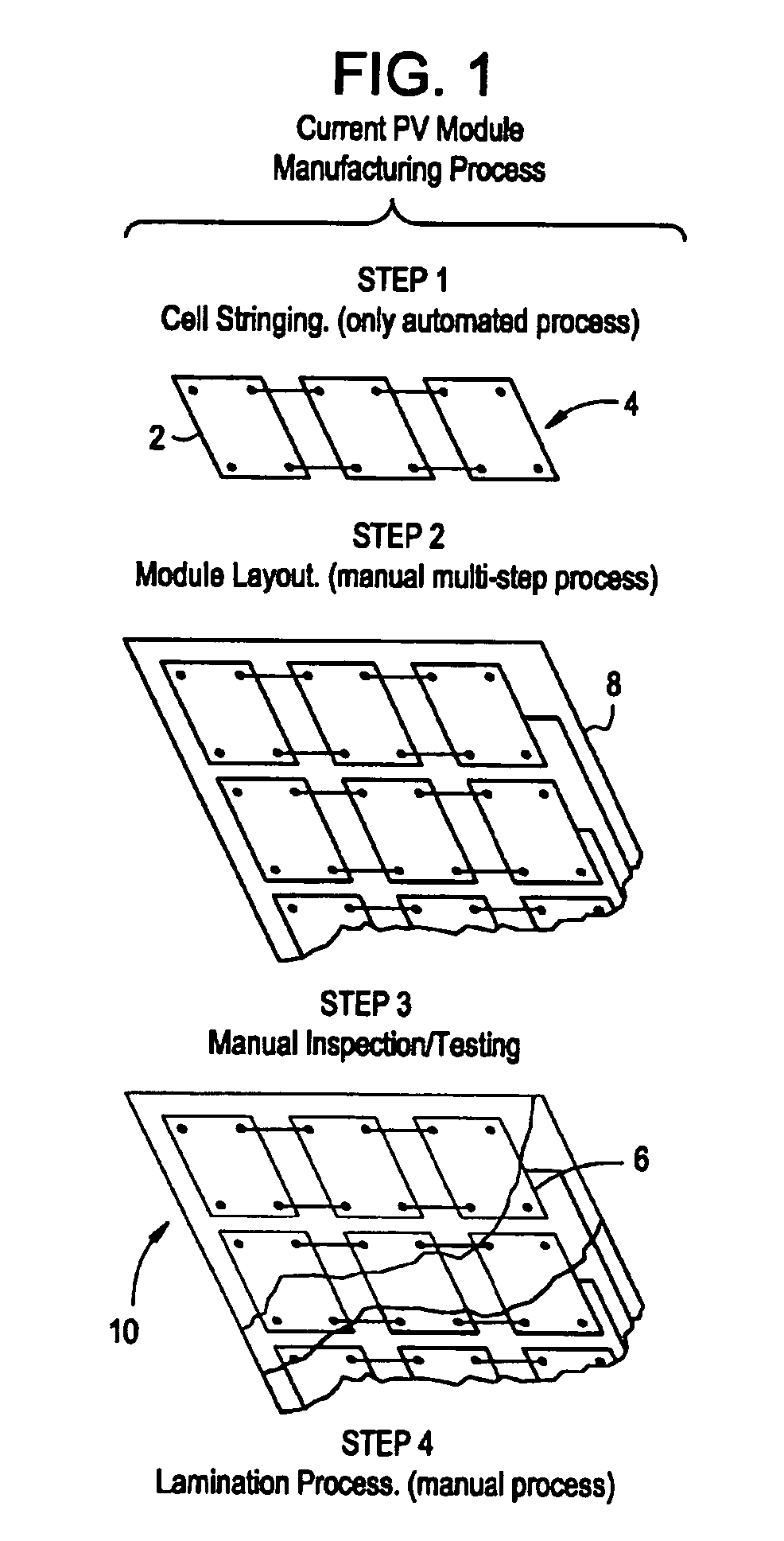
[0014] Referring to FIG. 1, a conventional procedure for fabrication of a photovoltaic module is illustrated. The procedure varies very little across the PV industry and has remained fundamentally the same for the past 15-20 years. Individual solar cells 2 (independent of the technology) are electrically interconnected into a series string 4 using a tabbing structure at step 1. Solder tabs (not shown) are applied to the individual cells 2 manually or using an automated tabbing machine or stringing machine. The string 4 is the building block of a PV laminate. The stringing process at step 1 involves physical handling of cells 2 which often results in cell breakage requiring manual repair. The strings are typically manually moved to a layup station where multiple strings are arranged onto a top glass 6 (see step 4) that is covered with a plastic sheet (not shown) that will serve as an encapsulating layer at step 2. This is usually a manual operation although some vendors have automate...


PUM


Abstract

A photovoltaic (PV) laminate backplane assembly includes an insulative substrate and a metal foil bonded to the insulative substrate on a first surface and is electrically receptive for mounting a solar cell on a second surface opposite the first surface. The metal foil includes a light concentrator disposed at exposed regions on the second surface of the metal foil and is configured to reflect incident light thereon to the solar cell to increase a concentration of light on the solar cell in a range of about 1.5× to about 4×.

Description

BACKGROUND OF THE INVENTION [0001] Providing electricity through photovoltaic (PV) cells is becoming more popular as this technology has decreased in cost and reliance on other sources of electric power is increasingly disfavored for environmental and strategic reasons. However, providing a cost effective PV module has been elusive since the cost of the PV module is dominated by the cost of the PV cells. [0002] Photovoltaics refer to cells that convert sunlight directly into electrical energy. The electricity produced is direct current that can be used as direct current, converted to alternating current through the use of an inverter, or stored for later use in a battery. Conceptually, in its simplest form, a photovoltaic device is a solar-powered battery whose only consumable is light. Because sunlight is universally available, photovoltaic devices have many advantages over traditional power sources. Photovoltaic systems are distributed power systems such that their electrical powe...

Claims


Application Information

Patent Timeline
IPC IPC(8): H01L25/00
CPCH01L31/052Y02E10/52H01L31/0547H01L31/056H02S20/00
Inventor KORMAN, CHARLES STEVEN
Owner GENERAL ELECTRIC CO
Why Eureka
Try Eureka