

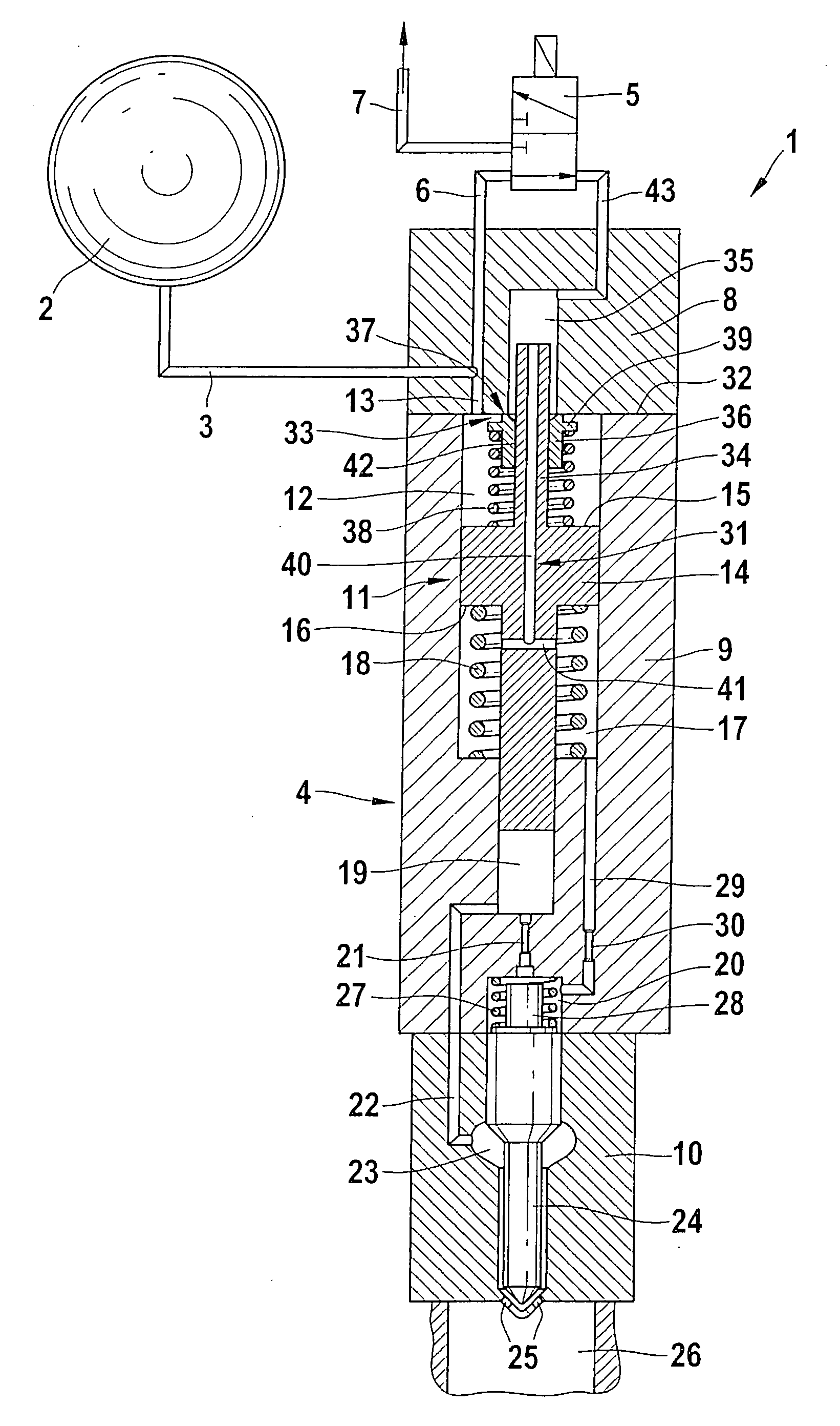
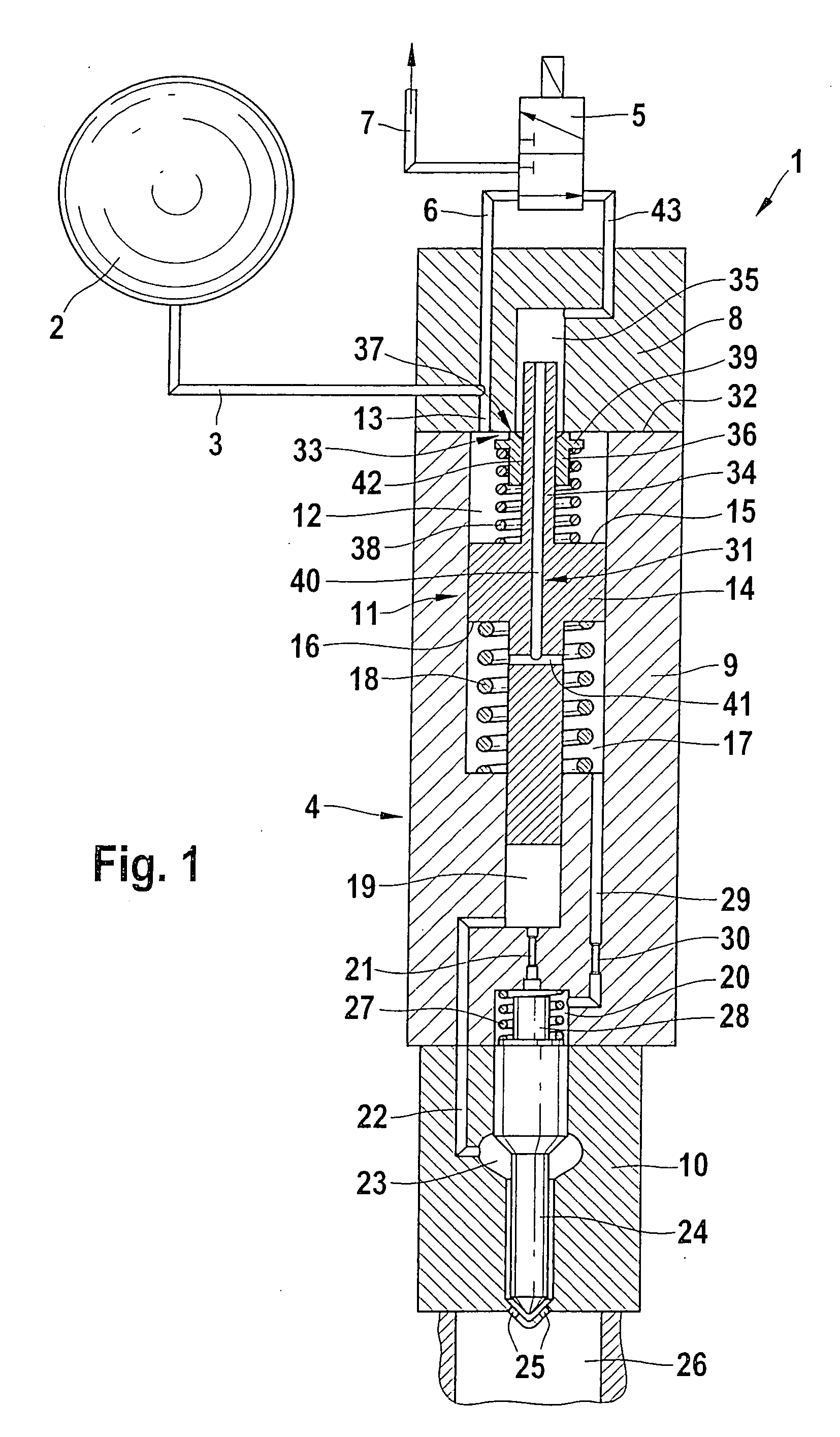
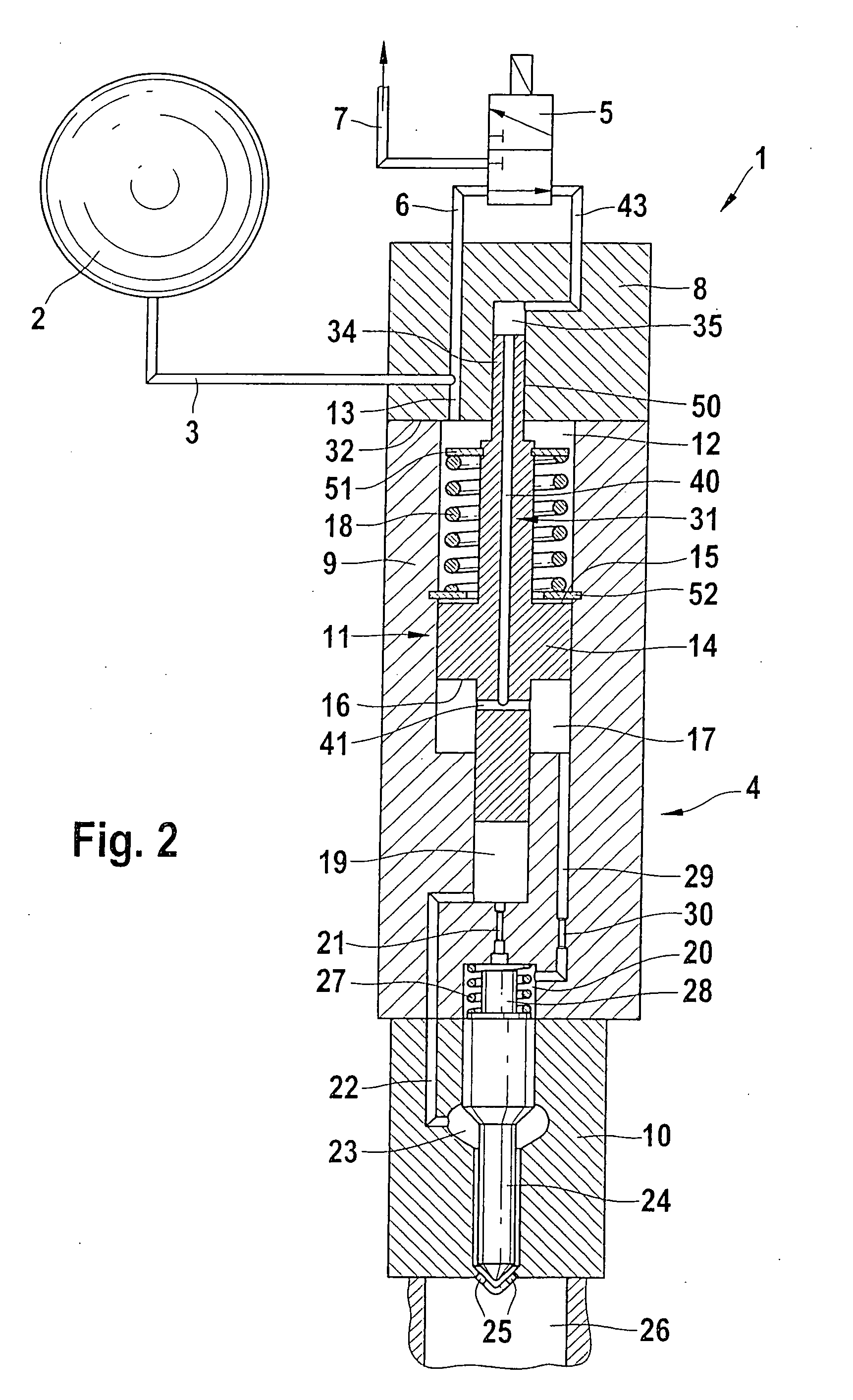
Pressure-boosted fuel injection device comprising an internal control line
a fuel injection device and fuel injection technology, applied in the direction of fuel injection apparatus, spraying apparatus, feeding system, etc., can solve the problems of high material stress at the bore intersection and costly machining steps
- Summary
- Abstract
- Description
- Claims
- Application Information
AI Technical Summary
Benefits of technology
Problems solved by technology
Method used
Image

Examples
Embodiment Construction
[0005] The design proposed according to the invention makes it possible to achieve an improvement in the high-pressure tightness of a fuel injector with a pressure booster. The elimination of a control line running along the outside of the fuel injector with pressure booster reduces the external dimensions of the fuel injector or avoids a placement of a pressure booster eccentric to the fuel injector.
[0006] A control line disposed in the booster piston and extending coaxial to the symmetry axis of the fuel injector advantageously avoids bore intersections of the kind that necessarily occur in external lines because of the connection location of the high-pressure connections and reduces material stresses, which in turn extends the service life of the fuel injector with pressure booster. The central control line, which is for relieving pressure in or exerting pressure on a differential pressure chamber used to actuate the pressure booster, extends through a pressure booster working c...
PUM
 Abstract
Description
Claims
Application Information