Semiconductor device

a technology of semiconductor devices and semiconductors, applied in semiconductor devices, semiconductor/solid-state device details, electrical apparatus, etc., can solve the problems of difficult to obtain dimensional accuracy that enables narrow pitch, circuit boards and heat sinks are restricted, and circuit boards and heat sinks are difficult to achieve narrow pitch. , to achieve the effect of low thermal resistance and efficient dissipation

Inactive Publication Date: 2006-03-02
FUJITSU SEMICON LTD
View PDF4 Cites 33 Cited by
  • Summary
  • Abstract
  • Description
  • Claims
  • Application Information

AI Technical Summary

Benefits of technology

[0016] According to one embodiment of the present invention, in a semiconductor device, a semiconductor element is thermally coupled directly to a heat dissipation member through an opening formed in a circuit board and an interpo...

Problems solved by technology

Accordingly, there is a problem in that the circuit board is restricted in material selection.
Further, since pressing is employed, there is a problem in that it is difficult to obtain dimensional accuracy that enables narrow pitch.
Accordingly, there is also a problem in that the circuit board and the heat sinks are restricted in material selection in the semiconductor device of Patent-Related Document 2.
Accordingly, there is a problem in that the solder balls are restricted in size and wire bonding is restricted ...

Method used


Image

  • Semiconductor device
  • Semiconductor device
  • Semiconductor device

Examples


second embodiment

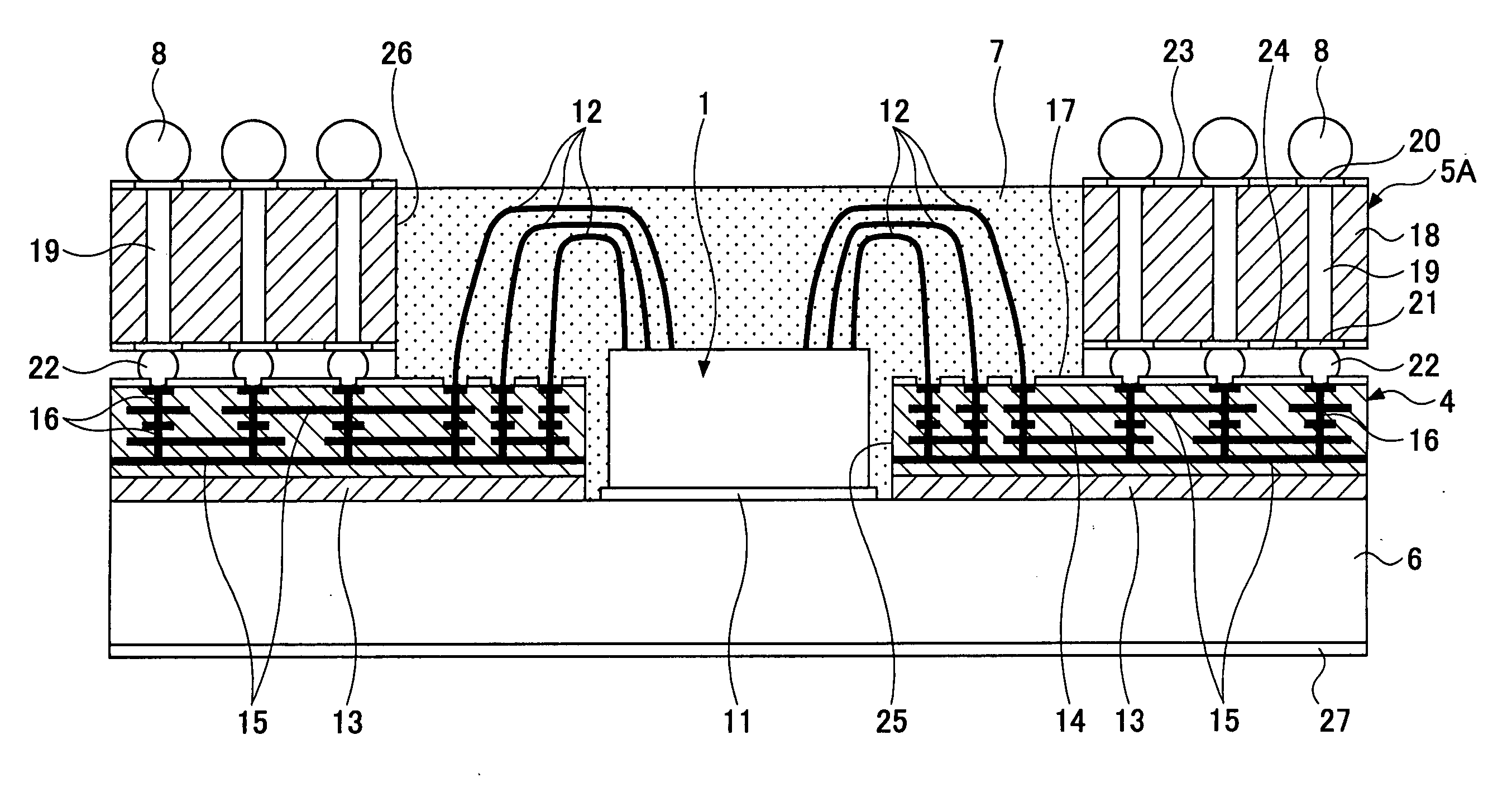
[0065] In the semiconductor device shown in FIG. 3, the semiconductor element 1 and a semiconductor element 2 are provided side by side in the opening 25. The connection between the semiconductor elements 1 and 2 and the circuit board 4 and the connection between the semiconductor elements 1 and 2 are established with the wires 12. According to the configuration of this embodiment, since the semiconductor elements 1 and 2 are provided side by side, the semiconductor device can be reduced in thickness.

[0066] In the semiconductor device according to the third embedment shown in FIG. 4, the semiconductor element 1 is mounted inside the opening 25, and the semiconductor element 2 is stacked on the semiconductor element 1. According to this embodiment, the semiconductor elements 1 and 2 are also connected to the circuit board 4 with the wires 12. According to the configuration of this embodiment, since the semiconductor elements 1 and 2 are stacked, the semiconductor device can be reduc...

fourth embodiment

[0067] In the semiconductor device shown in FIG. 5, the semiconductor elements 1 and 2 and a semiconductor element 3 are provided. The semiconductor elements 1 and 2 are provided side by side in the opening 25. The semiconductor element 3 is stacked on the semiconductor elements 1 and 2 so as to straddle the semiconductor elements 1 and 2. The semiconductor elements 1 and 2 are connected to the circuit board 4 with the wires 12. The semiconductor element 3 is connected to the semiconductor elements 1 and 2 by flip-chip bonding with bumps 28. This configuration enables the semiconductor device to be further sophisticated.

[0068] In the semiconductor device according to the firth embodiment shown in FIG. 6, the semiconductor element 2 is stacked on the semiconductor element 1. According to this embodiment, the semiconductor element 1 and the circuit board 4 are connected with the wires 12, and the semiconductor element 2 and the semiconductor element 1 are connected by flip-chip bondi...

sixth embodiment

[0069] In the semiconductor device shown in FIG. 7, the semiconductor element 2 is stacked on the semiconductor element 1. According to this embodiment, the semiconductor element 2 is shaped to be greater in size than the semiconductor element 1. Specifically, the semiconductor element 2 is shaped to be greater in size than the opening 25 formed in the circuit board 4. Accordingly, with the semiconductor element 2 being stacked on the semiconductor element 1, the semiconductor element 2 overlaps with the circuit board 4 so that the edge part of the semiconductor element 2 is over the circuit board 4.

[0070] The bumps 28 are also provided to the overlap between the semiconductor element 2 and the circuit board 4. Accordingly, the semiconductor element 2 is connected to both the semiconductor element 1 and the circuit board 4 by flip-chip bonding. According to this embodiment, the semiconductor element 1 and the circuit board 4 are connected via the semiconductor element 2.

[0071] In ...


PUM


Abstract

A semiconductor device is disclosed that includes a semiconductor element, a circuit board electrically connected to the semiconductor element, a heat dissipation member fixed to the first surface of the circuit board and thermally coupled to the semiconductor element, and an interposer provided to the second surface of the circuit board facing away from the heat dissipation member. The interposer is electrically connected to the circuit board. An opening is formed in the circuit board and the interposer so that the semiconductor element is thermally coupled directly to the heat dissipation member through the opening.

Description

CROSS-REFERENCE TO RELATED APPLICATION [0001] The present application is based on Japanese Priority Patent Application No. 2004-253112, filed on Aug. 31, 2004, the entire contents of which are hereby incorporated by reference. BACKGROUND OF THE INVENTION [0002] 1. Field of the Invention [0003] The present invention generally relates to semiconductor devices, and more particularly to a semiconductor device including a heat dissipation member that dissipates heat generated in a semiconductor element. [0004] 2. Description of the Related Art [0005] In recent years, semiconductor elements provided inside semiconductor devices have become higher in density and speed. As a result, the amount of heat generated during operation has been on the increase. On the other hand, there is a demand for smaller semiconductor devices. [0006] Accordingly, there is a demand for a semiconductor device that can dissipate heat generated in a semiconductor element with efficiency while being reduced in size...

Claims


Application Information

Patent Timeline
IPC IPC(8): H01L23/34
CPCH01L23/13H01L23/36H01L23/492H01L23/49816H01L23/49822H01L23/49827H01L23/49833H01L24/49H01L25/0652H01L25/0655H01L25/0657H01L2224/16145H01L2224/16225H01L2224/16237H01L2224/32145H01L2224/48091H01L2224/48095H01L2224/48137H01L2224/48145H01L2224/48227H01L2224/48228H01L2224/48235H01L2224/49H01L2224/73207H01L2224/73265H01L2225/06506H01L2225/0651H01L2225/06513H01L2225/06517H01L2225/06555H01L2225/06586H01L2924/01004H01L2924/01005H01L2924/01006H01L2924/01013H01L2924/01028H01L2924/01029H01L2924/01074H01L2924/09701H01L2924/15153H01L2924/1517H01L2924/15192H01L2924/15311H01L2924/1532H01L2924/15321H01L2924/19041H01L2924/19107H01L2924/3011H01L2924/3025H01L24/48H01L2924/01019H01L2924/01033H01L2924/014H01L2224/32245H01L2924/00014H01L2924/00012H01L2924/181H01L24/73H01L2924/00011H01L2224/45099H01L2224/05599H01L2224/0401
Inventor TAMAGAWA, MICHIAKISUZUKI, TAKUYASASAKI, HIROYUKI
Owner FUJITSU SEMICON LTD
Why Eureka
Try Eureka