
Dual spring jounce bumper assembly

a bumper and spring technology, applied in the direction of shock absorbers, mechanical equipment, transportation and packaging, etc., can solve the problems of increasing the load that passes through the jounce bumper, limiting the wheel size and unsprung mass, and high peak strut load, so as to reduce the progressive nonlinear character increase the peak load performance of the jounce bumper, and reduce the peak load the jounce bumper generates

Inactive Publication Date: 2006-03-02
GENERAL MOTORS COMPANY
View PDF18 Cites 61 Cited by
  • Summary
  • Abstract
  • Description
  • Claims
  • Application Information

AI Technical Summary

Benefits of technology

[0013] One advantage of the present invention is that a dual spring jounce bumper assembly is provided for a suspension system of a vehicle to greatly enhance peak load performance of a jounce bumper by reducing the peak loads the jounce bumper generates. Another advantage of the present invention is that the dual spring jounce bumper assembly reduces the progressive nonlinear character of a jounce bumper offering potential ride improvements. Yet another advantage of the present invention is that the dual spring jounce bumper assembly provides a low cost solution for substantially improving the ability of jounce bumpers to reduce peak loads. Still another advantage of the present invention is that the dual spring jounce bumper assembly provides significant improvement of ride quality, stability, and reliability of the vehicle. A further advantage of the present invention is that the dual spring jounce bumper assembly provides a savings on vehicle weight and decreases the unsprung mass. Yet a further advantage of the present invention is that the dual spring jounce bumper assembly is very reliable and durable and provides significantly smaller loads acting on the vehicle body.

Problems solved by technology

This is undesirable for loads management and gives rise to high peak strut loads, particularly as a result of potholes in the road surface.
These high peak loads may limit wheel size and unsprung mass, both of which can result in increases in the load that passes through the jounce bumper, all else being equal.
Otherwise, increased unsprung mass and wheel size could require costly structural reinforcements to the strut upper mount vehicle structure.
Standard jounce bumpers can also generate undesirable ride characteristics as a result of their highly progressive rates.
The response of the vehicle suspension system to a very stiff or progressive rate is often characterized as harsh or lacking in good energy management.

Method used


Image

  • Dual spring jounce bumper assembly
  • Dual spring jounce bumper assembly
  • Dual spring jounce bumper assembly

Examples


Embodiment Construction

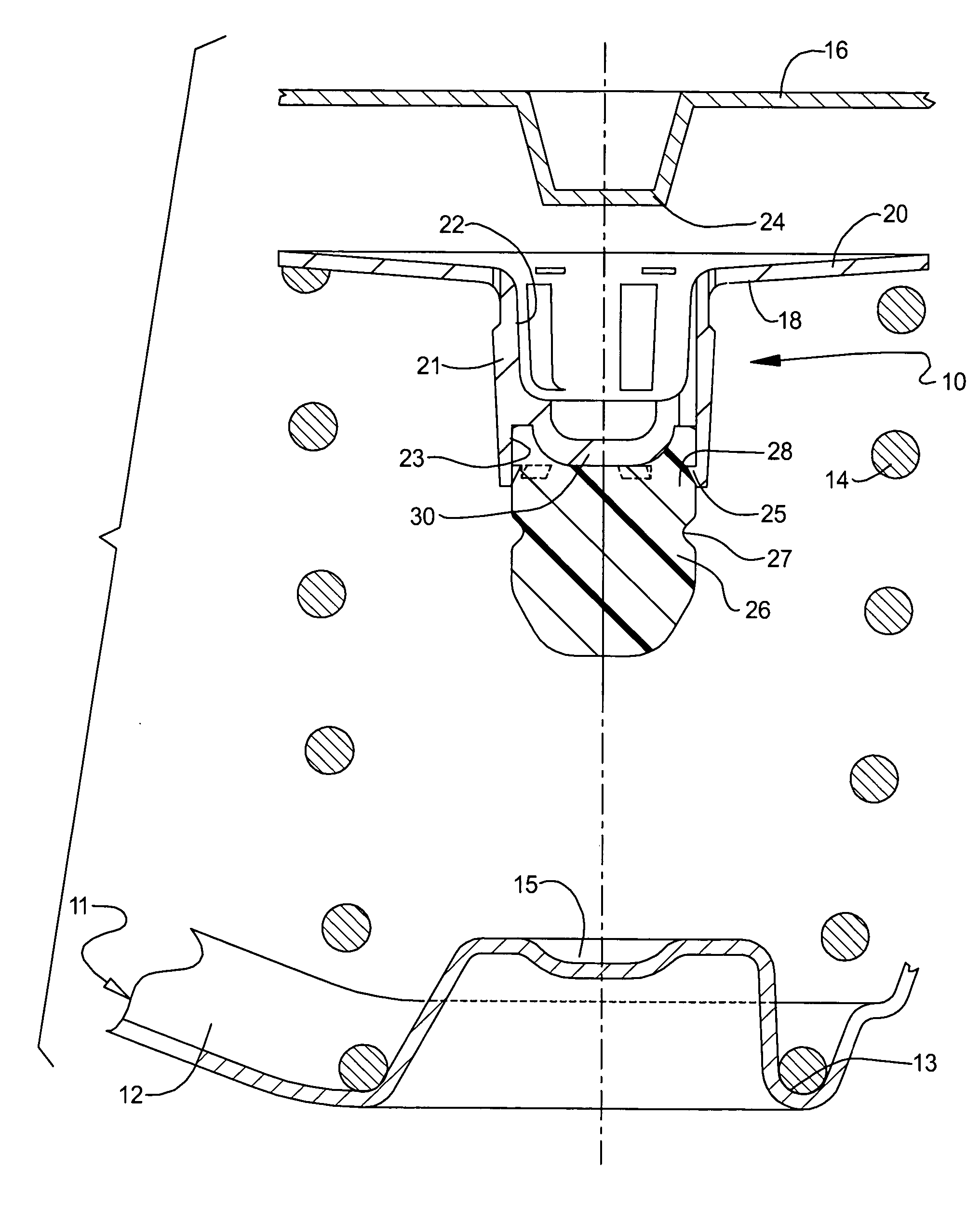
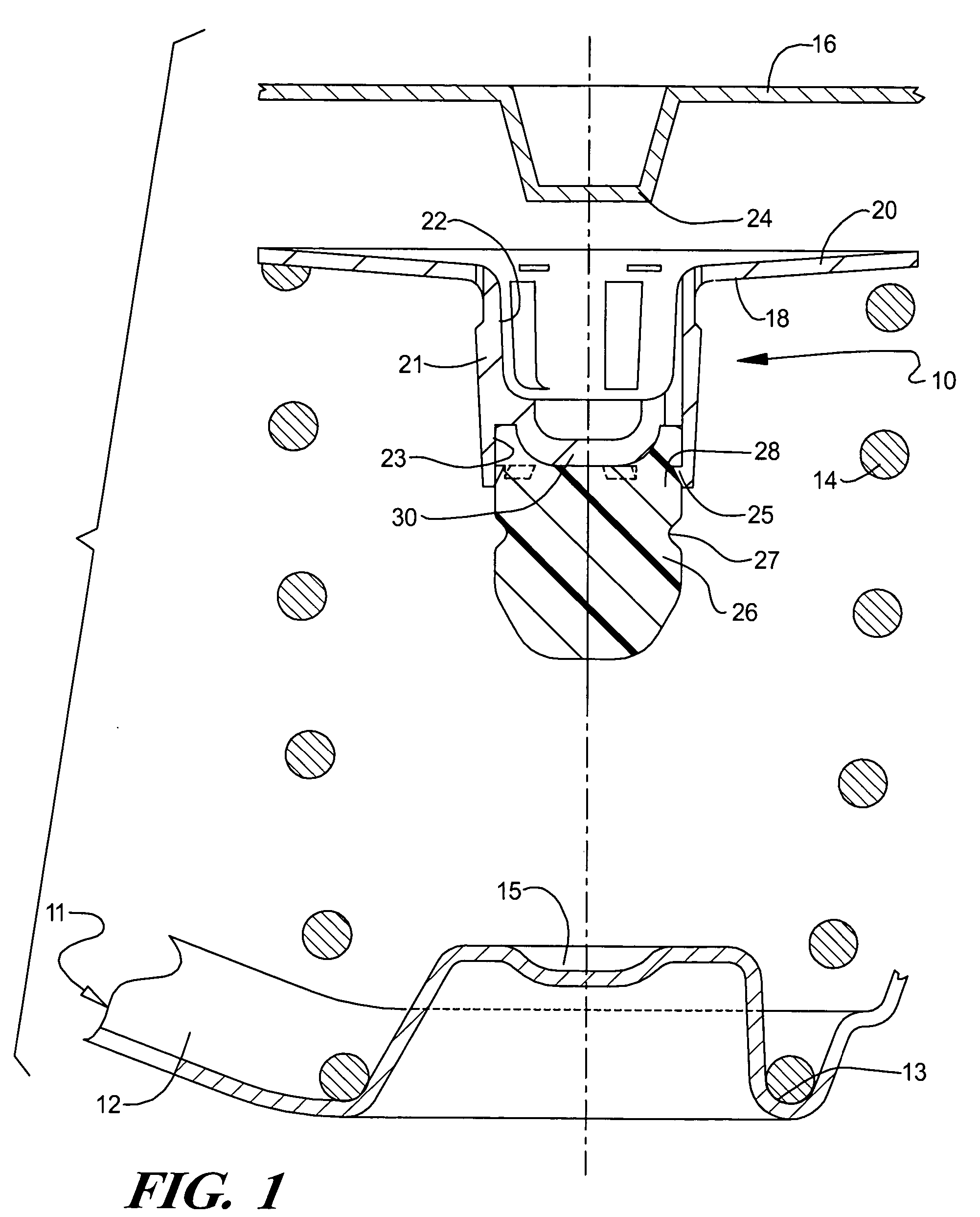
[0022] Referring to the drawings and in particular FIG. 1, one embodiment of a dual spring jounce bumper assembly 10, according to the present invention, is shown for a suspension system, generally indicated at 11, of a vehicle (not shown). The suspension system 11 is operatively connected between an unsprung portion (not shown) and a sprung portion (not shown) of the vehicle in a well-known manner.

[0023] The suspension system 11 includes a lower control arm 12 having a spring seat 13. The suspension system 11 includes a coil spring 14 having a lower end that rests in the spring seat 13. The suspension system 11 includes a bumper stop 15 radially inward of the spring seat 13 against which the jounce bumper assembly 10 contacts during full contraction of the suspension system 11. The suspension system 11 includes an upper spring seat 16 against which the dual spring jounce bumper assembly 10 sits. It should be appreciated that, except for the dual spring jounce bumper assembly 10, t...


PUM


Abstract

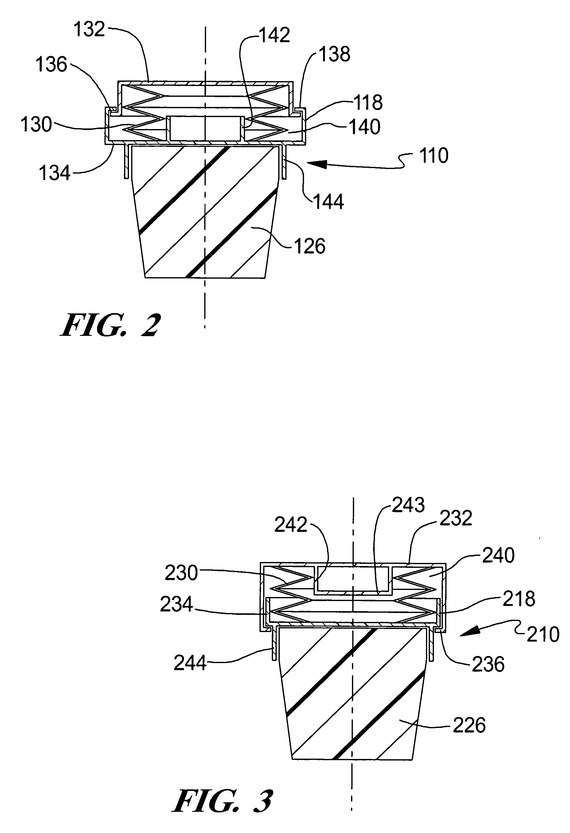
A dual spring jounce bumper assembly for a vehicle includes a jounce bumper adapted to be mounted in the suspension system and a spring disposed in series with the jounce bumper to reduce jounce bumper rate progressivity and peak loads in the jounce bumper.

Description

TECHNICAL FIELD [0001] The present invention relates generally to suspension systems for vehicles and, more particularly, to a dual spring jounce bumper assembly for a suspension system of a vehicle. BACKGROUND OF THE INVENTION [0002] It is known to provide a suspension system for a vehicle such as a motor vehicle. One form of the suspension system includes a coil spring seated in a lower seat in a wheel assembly and seated in an upper seat in a vehicle body or frame of the vehicle. The spring supports the weight of the vehicle and allows for reciprocating relative movement between a vehicle wheel and vehicle during road travel to isolate wheel disturbances from the vehicle body. Typically, a form of stop is provided between the vehicle wheel or axle and the vehicle body to limit travel of the wheel in the direction of the body and to prevent a metal surface of the wheel or axle from “bottoming out” against the vehicle body. These stops are typically made of rubber or plastic uretha...

Claims


Application Information

Patent Timeline
IPC IPC(8): B60G13/00
CPCB60G7/04B60G11/16B60G11/54F16F9/58B60G2202/143B60G2204/124B60G2204/4502B60G2202/12
Inventor GOFRON, MARIANSCHUDT, JOSEPH A.WALKER, STEPHEN I.GEISLER, ROBERT LOUIS
Owner GENERAL MOTORS COMPANY
Learn More