Permanent magnet assisted synRM and method for imposing magnetic force thereon

a technology of permanent magnets and synrms, which is applied in the direction of magnetic circuit rotating parts, magnetic bodies, magnetic circuit shapes/forms/construction, etc., can solve the problems of increasing and achieve the reduction of the amount of magnets consumed, the effect of increasing the efficiency of pma synrms and reducing the production cost of pma synrms

Active Publication Date: 2006-03-02
LG ELECTRONICS INC
View PDF26 Cites 40 Cited by
  • Summary
  • Abstract
  • Description
  • Claims
  • Application Information

AI Technical Summary

Benefits of technology

[0023] Therefore, the present invention has been made in view of the above problems, and it is an object of the present invention to provide a PMA synRM, which comprises a sufficiently large number of flux barriers and a decreased amount of magnets consumed, inserted into the flux barriers, when a magnetic force is imposed on the magnets, and a method for imposing a magnetic force thereon, thereby increasing the efficiency of the PMA synRM and reducing the production costs of the PMA synRM.

Problems solved by technology

However, in case that a large number of the flux barriers 3 are formed in the rotor 2, the magnets 3a, which are inserted into all of the flux barriers 3, cause an increase of production costs of the PMA synRM.

Method used


Image

  • Permanent magnet assisted synRM and method for imposing magnetic force thereon
  • Permanent magnet assisted synRM and method for imposing magnetic force thereon
  • Permanent magnet assisted synRM and method for imposing magnetic force thereon

Examples


first embodiment

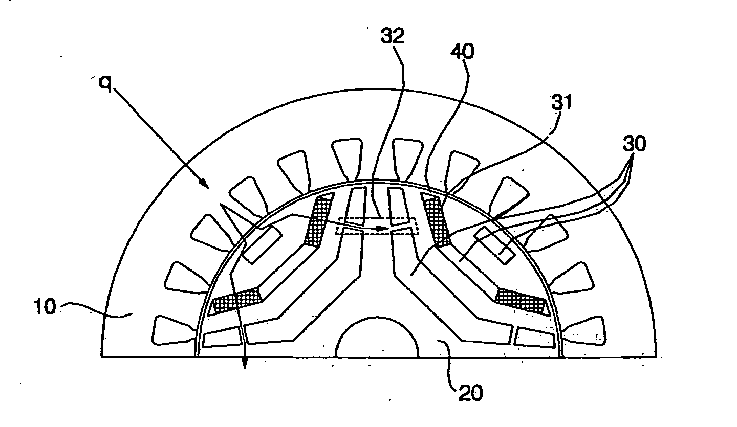
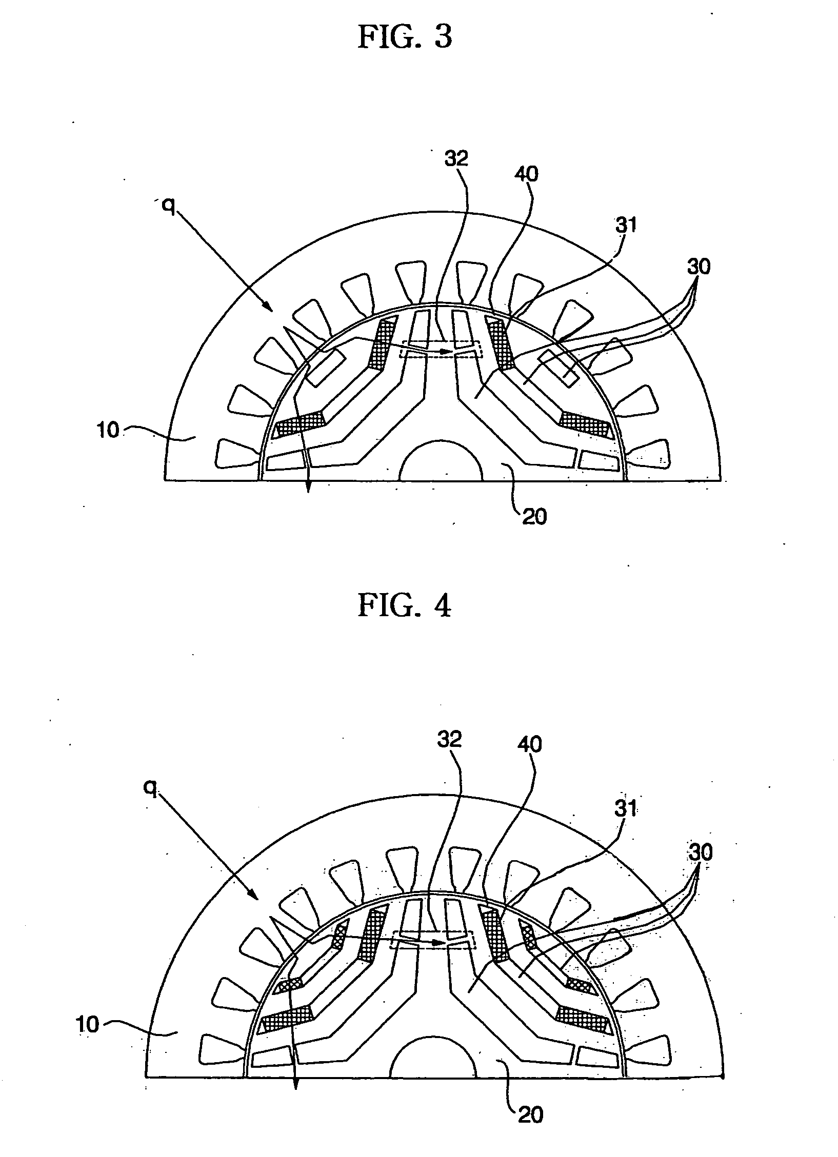
[0047] FIGS. 3 to 6 are partial cross-sectional views illustrating a stator and a rotor of a PMA synRM in accordance with the present invention. Here, the arrows shown in FIGS. 3 to 6 denote the routes of magnetic flux.

[0048] The PMA synRM in accordance with the first embodiment of the present invention comprises a stator 10, a rotor 20, magnets 31, which are inserted into portions of outer flux barriers 30 of a plurality of flux barriers 30 formed along the radius of the stator 20, and bridges 32 formed on the inner flux barriers 30 at positions corresponding to the positions of the magnets 31 inserted into the outer flux barriers 30.

[0049] Particularly, in FIGS. 3 and 4, the magnets 31 are inserted into both sides of the outer flux barriers 30 located in the outer portions of the rotor 20, and the bridges 32 are formed at both sides of the inner flux barriers 30, located in the inner portions of the rotor 20, at positions corresponding to the positions of the magnets 31.

[0050] M...

second embodiment

[0067]FIGS. 7 and 8 are partial cross-sectional views of a PMA synRM in accordance with the present invention. Here, the arrows shown in FIGS. 7 and 8 denote routes of magnetic flux.

[0068] In the PMA synRM in accordance with the second embodiment, magnets 31b are inserted into sides of outer flux barriers 30 of a plurality of flux barriers 30 formed along the radius of the stator 20, and slim portions 32b having a low thickness are formed on inner flux barriers 30 at positions corresponding to the positions of the magnets 31b.

[0069] In the same manner as the first embodiment of the present invention, the magnets 31b of the PMA synRM of the second embodiment, which are inserted into the outer flux barriers 30, may have various positions. In FIG. 7, the magnets 31b are inserted into both sides of the outer flux barriers 30, and the slim portions 32b having a low thickness are formed at both sides of the inner flux barriers 30 at positions corresponding to the positions of the magnets...


PUM

PropertyMeasurementUnit
radiusaaaaaaaaaa
magnetic fluxaaaaaaaaaa
magnetic forceaaaaaaaaaa

Abstract

A PMA (Permanent Magnet Assisted) synRM and a method for imposing a magnetic force thereon. Magnets are inserted into outer flux barriers of a plurality of flux barriers formed along the radius of a rotor, and bridges or slim portions are formed on inner flux barriers at positions corresponding to the positions of the magnets so that the magnetic force is imposed on the magnets through coils. Since the number of the flux barriers is sufficiently increased while the amount of the magnets consumed is decreased, the PMA synRM has increased efficiency and reduced production costs.

Description

BACKGROUND OF THE INVENTION [0001] 1. Field of the Invention [0002] The present invention relates to a permanent magnet assisted (hereinafter, referred to as “PMA”) synchronous reluctance motor (hereinafter, referred to as “synRM”) and a method for imposing a magnetic force thereon, and more particularly to a PMA synRM, which is connected to a compressor, and comprises a sufficiently large number of flux barriers formed in a rotor and a decreased number of magnets inserted into the flux barriers, and a method for imposing a magnetic force thereon. [0003] 2. Description of the Related Art [0004] Now, with reference to FIGS. 1 and 2, the structures of a conventional synRM and a conventional PMA synRM will be described. [0005]FIG. 1 is a partial cross-sectional view of the conventional synRM. As shown in FIG. 1, the conventional synRM comprises a stator 1, and a rotor 2 rotatably installed in the stator 1 and synchronously rotated to minimize the magnetic reluctance by a reluctance tor...

Claims


Application Information

Patent Timeline
Patent Type & Authority Applications(United States)
IPC IPC(8): H02K21/12H01F13/00H02K1/27H02K15/03H02K19/10
CPCH01F13/003H02K15/03H02K1/2766H02K1/246H02K19/02
Inventor CHEONG, DAL HOLEE, KYUNG HOONSHIN, HYUN HUNWON, JUNE HEEOH, JAE YOONLEE, GIL SU
Owner LG ELECTRONICS INC
Why Eureka
Try Eureka