Emi measuring method and its system

a technology of electromagnetic interference and measuring method, applied in the direction of resistance/reaction/impedence, measurement device, instruments, etc., can solve the problems of difficult to trace out the source of electromagnetic interference and remove, large increase in cost, and circle board inside, etc., to shorten the product development period, simple method and system structure, easy to operate

Inactive Publication Date: 2006-03-02
WU WEI
View PDF7 Cites 22 Cited by
  • Summary
  • Abstract
  • Description
  • Claims
  • Application Information

AI Technical Summary

Benefits of technology

[0008] Compared with prior art, the present invention method and its system have prominent advantages. By means of tracing out EMI physical position and tracing out components that possibly generate EMI, the invention method and its system indicate a right approach for reducing EMI and shorten the product developing period. The computer based processing, converting, comparing and analysing system are flexible and independent from the ambien

Problems solved by technology

As the EMC status of a new product is unforeseeable, it is normal for a product to fail the EMC test after its prototype is ready and goes to EMC lab for test.
Usually, the prototype has to be reproduced as the Printed Circle Board inside the prototype is mostly unchangeable.
It is very di

Method used


Image

  • Emi measuring method and its system
  • Emi measuring method and its system
  • Emi measuring method and its system

Examples


Embodiment Construction

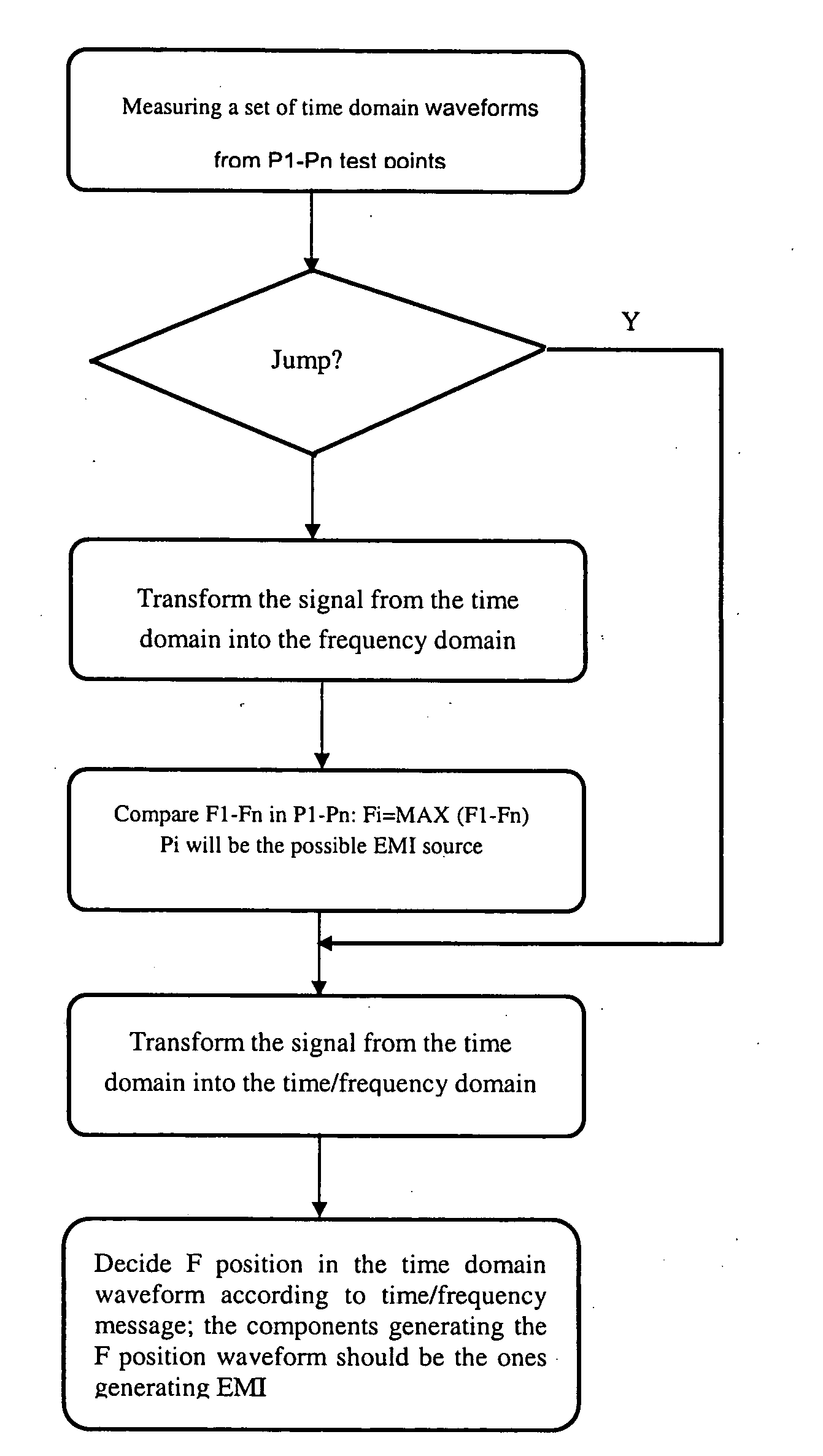
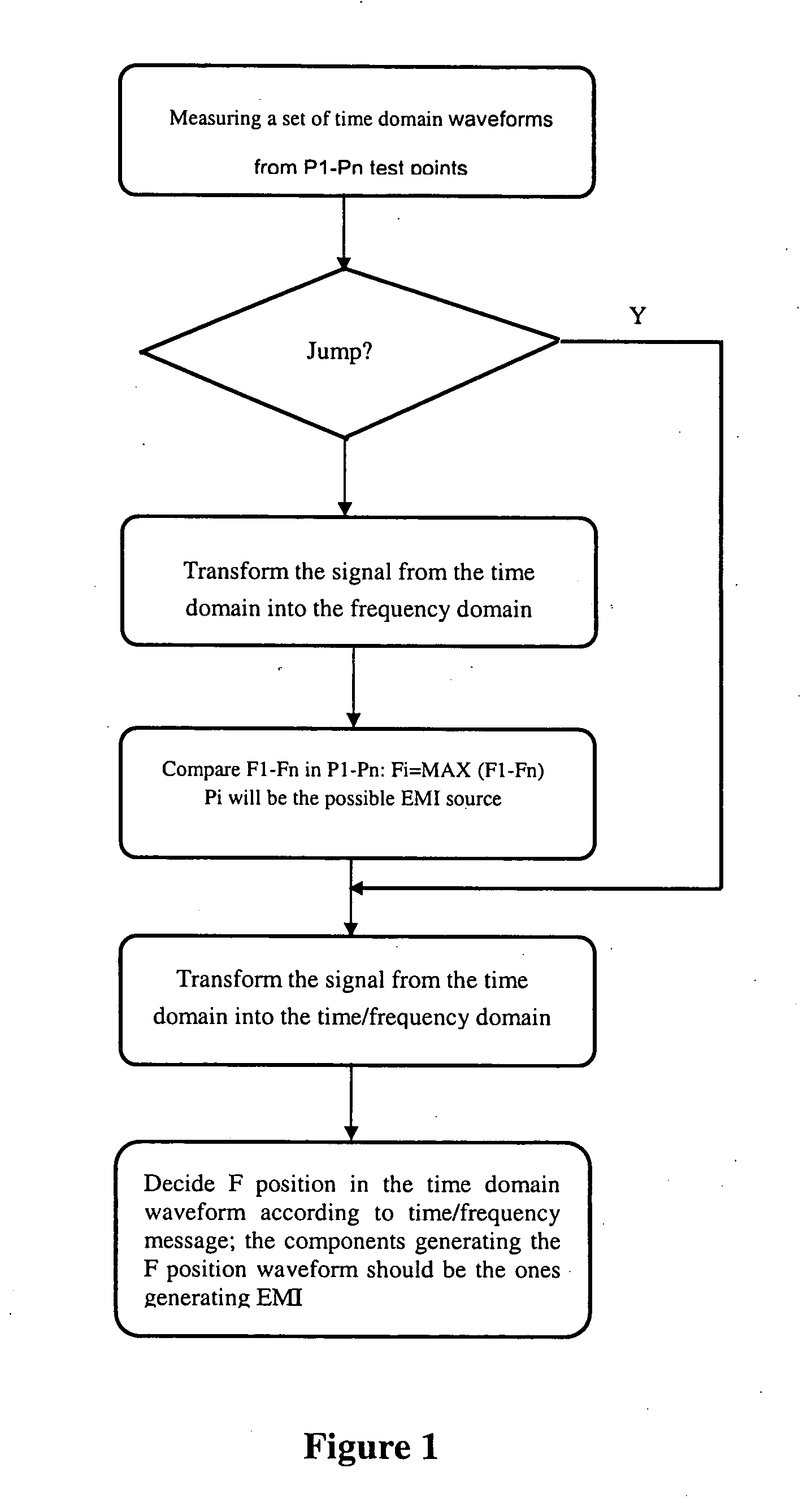
[0014]FIG. 1 is a flow chart of the EMI diagnosis method and the process of the invention method comprising:

[0015] (1) To obtain a set of time domain waveforms from a group of equably distributed test points (P1 . . . Pn) on an EUT. The waveform can be current waveform, or voltage waveform, or electromagnetic field intensity waveform.

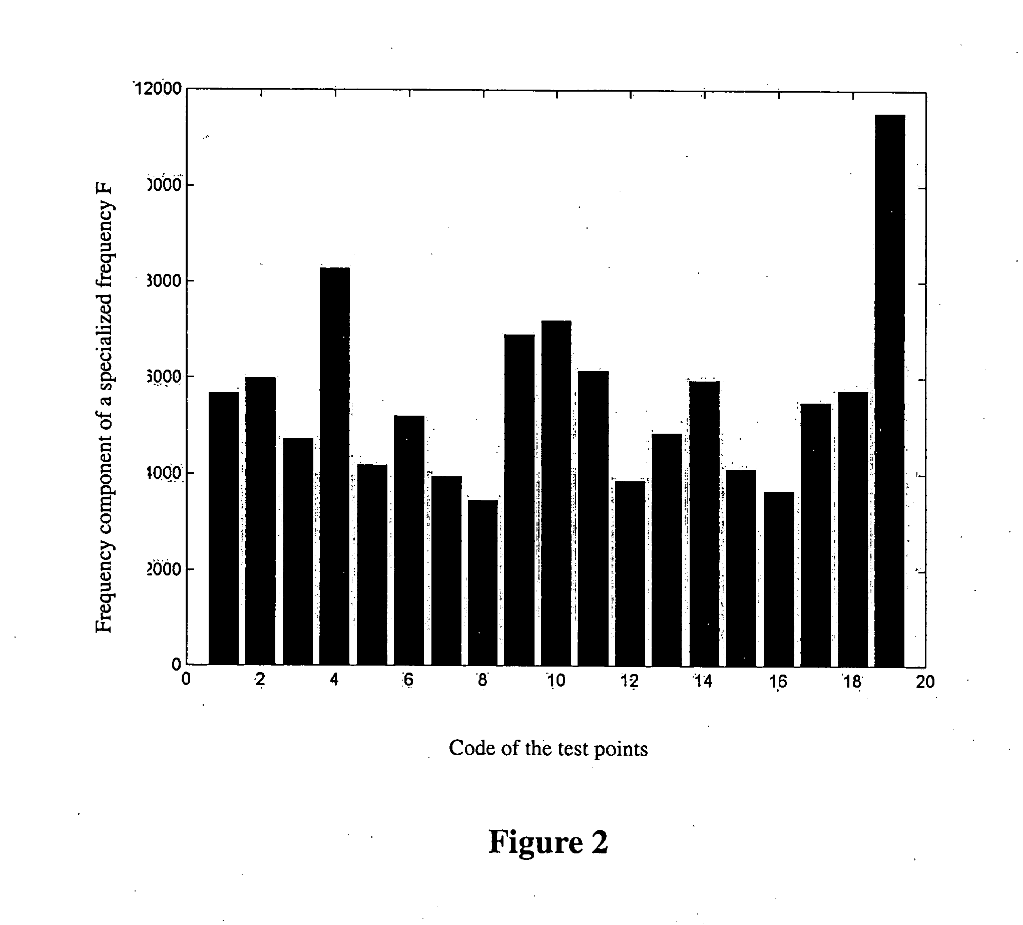
[0016] (2) To transform the above time-domain-signals into the frequency-domain-signals, as shown in FIG. 2. Alternatively, to transform the signals into time / frequency-domain-signals, as shown in FIG. 3.

[0017] The said “transforming the time-domain-signal into the frequency-domain-signal” can be achieved by means of Fourier Transform: f^⁡(ω)=∫-∞+∞⁢f⁡(t)⁢ⅇ-ⅈω⁢ ⁢t⁢ⅆt[0018] where [0019] f(t) is the time domain signal being transformed; [0020] {circumflex over (f)}(ω) is the spectrum after transforming; [0021] Or by means of Wavelet Transform: Wf⁡(u,s)=f,ψu,s,>=∫-∞∞⁢f⁡(t)⁢1s⁢ψ*⁡(t-us)⁢ⅆt[0022] where [0023] S is the scale factor; [0024] U is the shifti...


PUM


Abstract

An electromagnetic interference (EMI) measuring method and its system for diagnosing EMI of various electronic devices and instructing user to improve design to satisfy Electromagnetic Compatibility (EMC) criterion. The measuring method according to the present invention includes acquiring a set of time domain signal waveforms from a group of uniformly distributed test points on equipment under test (EUT), and then processing, converting, comparing and analysing, and finally determining physical position of EMI on EUT. To implement the present method, the present invention provides an EMI measuring system. The system includes signal acquisition portion and signal analysis portion. The signal analysis portion takes computer as carrier, which establishes processing, converting, comparing and analysing modules on operating system platform of computer. The method steps and system structure according to the present invention are simple and convenient which are no restricted by ambience and the measuring result is reliable.

Description

FIELD OF THE INVENTION [0001] The present invention relates to an Electromagnetic Interference (EMI) measuring method and its system. BACKGROUND OF THE INVENTION [0002] The level of Electromagnetic Interference (EMI) or its ability of anti-electromagnetic-interference is a very important parameter to evaluate an electronic product. With the enforcement of the Electromagnetic Compatibility (Amendment) Regulations 1995 (EMCR) in 1996, all the electromagnetic products must meet the Europe EMCR requirement before being sold in Europe market. China also issued its Electromagnetic Compatibility (EMC) criterion in 2001. EMC diagnosis, however, requires high technology, which sometimes is more sophisticated than the manufacture itself. As the EMC status of a new product is unforeseeable, it is normal for a product to fail the EMC test after its prototype is ready and goes to EMC lab for test. The prototype has to be returned to workshop for modification. Usually, the prototype has to be rep...

Claims


Application Information

Patent Timeline
IPC IPC(8): G01R27/28G01R31/00
CPCG01R31/002G01R31/001
Inventor WU, WEI
Owner WU WEI
Why Eureka
Try Eureka