Serial signal injection using capacitive and transformer couplings for power line communications

Inactive Publication Date: 2006-03-02
AVAGO TECH WIRELESS IP SINGAPORE PTE
View PDF10 Cites 60 Cited by
  • Summary
  • Abstract
  • Description
  • Claims
  • Application Information

AI Technical Summary

Problems solved by technology

However, using multiple PLMs with parallel signal injection, whether transformer coupled or capacitively coupled, undesirably loads the signals to and from a PLM when used with a standard power supply incorporating a filter capacitor.

Method used


Image

  • Serial signal injection using capacitive and transformer couplings for power line communications
  • Serial signal injection using capacitive and transformer couplings for power line communications
  • Serial signal injection using capacitive and transformer couplings for power line communications

Examples


Embodiment Construction

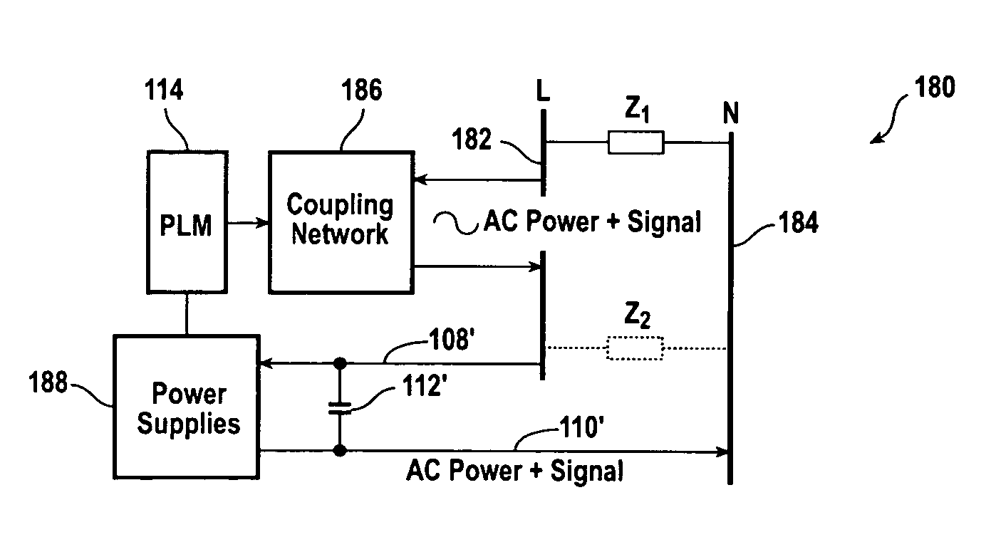
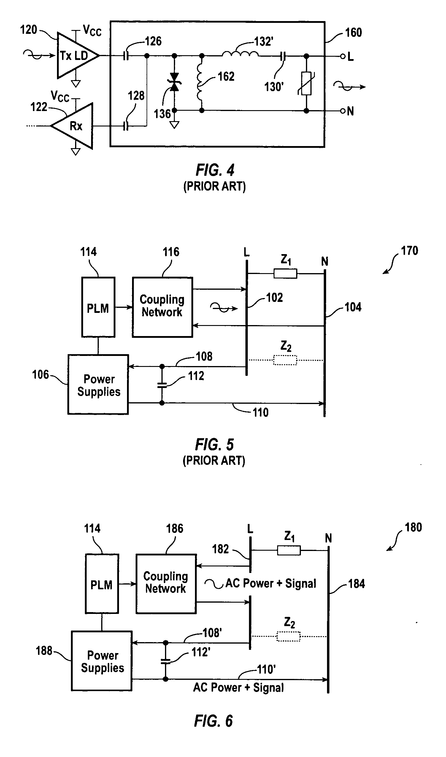
[0024]FIG. 5 is a diagram of a prior art PLC system 170 illustrating a problem arising when a PLM using a coupling network with parallel signal injection is connected to power lines 102, 104. The EMI filter capacitor 112 has a capacitance selected to couple EMI from one power supply lead 108 to the other power supply lead 110. In other words, the capacitance is high enough, typically greater than about 1 nF and more typically about 100 nF, to couple EMI at the lowest frequency of interest. The lowest EMI frequency may be lower than, or about the same as, the signal frequency, and the filter capacitor 112 has the undesirable effect of reducing the impedance of the effective (i.e. total) load on the coupling network 116.

[0025] For example, Z1 is the impedance of the load end of the power lines 102, 104, which represents the loads of other nodes (e.g., connected appliances, such as additional PLMs) on the power lines. It is generally desirable to keep the load impedance as high as pos...


PUM


Abstract

A coupling network has a first power line interface port and a power line modem interface configured to be coupled to a power line modem transceiver. An inductor-capacitor circuit coupled to the power line modem interface has a low-impedance resonant frequency at a signal frequency of the power line modem transceiver. An inductor having a corner frequency between the signal frequency and the power line frequency has a first end and a second end. The first end of the inductor is connected to the inductor-capacitor circuit and a second end of the inductor is coupled to an alternating current ground coupled to the transceiver ground. The inductor couples the first power line interface port to a power supply interface port.

Description

CROSS-REFERENCE TO RELATED APPLICATIONS [0001] Not applicable. STATEMENT REGARDING FEDERALLY SPONSORED RESEARCH OR DEVELOPMENT [0002] Not applicable. REFERENCE TO MICROFICHE APPENDIX [0003] Not applicable. BACKGROUND OF THE INVENTION [0004] Power line communication (“PLC”) systems use electrical power lines to exchange information between electronic devices in a network, such as between computers or shared electronic devices. Power line modems (“PLMs”) are used in PLC systems to connect electronic devices in a home, office, building, or inter-building computer network and similar applications. [0005] PLMs typically have a receiver and one or more transmitter line drivers that are coupled to the power lines through a coupling network. The PLM is often powered by a power supply(s) coupled to the power lines. The power lines typically operate at a voltage level that is dangerous, such as 120 VAC or 230 VAC. It is important to protect the user of devices connected to the power supply fr...

Claims


Application Information

Patent Timeline
Patent Type & Authority Applications(United States)
IPC IPC(8): H03H7/48H03H1/00H04B3/56
CPCH04B2203/5491H04B3/56
Inventor LAW, ROBINSON PENG SENG
Owner AVAGO TECH WIRELESS IP SINGAPORE PTE
Why Eureka
Try Eureka