Windings for electrical machines

a technology of windings and electrical machines, applied in the direction of dynamo-electric machines, electrical apparatus, variable inductance/transformers, etc., can solve the problems of increasing the resistance of the conductor, increasing the cost of the winding, so as to avoid an unnecessary increase in the dc loss and minimize the ac loss

Inactive Publication Date: 2006-03-02
SWITCHED RELUCTANCE DRIVES
View PDF2 Cites 5 Cited by
  • Summary
  • Abstract
  • Description
  • Claims
  • Application Information

AI Technical Summary

Benefits of technology

[0016] Embodiments of the present invention provide a coil for an electrical machine which is made up of at least two sub-coils. In this way the designer is able to optimize the distribution of turns between the sub-coils to balance the DC and AC loss considerations according to the proportion of turns in one sub-coil relative to the other(s). The sub-coils are connected in series, according to one example, to ensure that they carry the same current. Such embodiments of the invention provide a technique for substantially minimizing the AC loss in those turns where the AC loss is highest while avoiding an unnecessary increase in the DC loss in other turns of the winding.

Problems solved by technology

When a current, I, flows in the winding of an electrical machine, there is a power loss due to the resistance of the conductor.
However, when the conductor is exposed to time-varying magnetic fields, the situation is considerably more complex.
All of the above give rise to circulating currents within the conductor, called “eddy currents” and hence produce additional loss in the conductor.
It can be many times the DC loss in the conductor.
Some electrical machines are more susceptible to this loss than others, e.g. those with magnetically salient structures have magnetic field patterns which have a high rate of change due to the motion of the rotor.
Large, low-voltage and fast electrical machines tend to require relatively large cross sectional areas for their conductor and to require relatively few turns per coil.
This leads to coils made up of a few turns of large-section conductor—an arrangement which exacerbates the creation of AC loss.
However, this immediately increases the DC loss in the coil.
Of course, the requirement to insulate the strands from each other brings an immediate penalty in that the space required for the insulation is generally taken from that otherwise available for the conductor cross-section, so the effective cross-section of the conductor is reduced.
Simple stranding as described above, however, may introduce other problems of circulating currents.
Although the voltage may be small, the effective resistance of the path is also small, so large circulating currents can be generated, leading to large losses.
While this can be achieved with relative ease on small machines using thin conductors, the production of coils for larger machines using large conductors can be extremely costly.
This process accounts for a significant part of the overall machine cost.
The twisting or weaving can be simple, but is often complex.
However, the use of litz wire has two drawbacks.
First, the cost of the cable is high, so using it for a large machine would entail considerable cost.
Second, because it is typically finely stranded, it has a poor ratio of conductor to overall space occupied, even if compacted after weaving, i.e. its DC resistance is high relative to the total cross section of the conductor, thus increasing the zero-frequency loss.

Method used


Image

  • Windings for electrical machines
  • Windings for electrical machines
  • Windings for electrical machines

Examples


Embodiment Construction

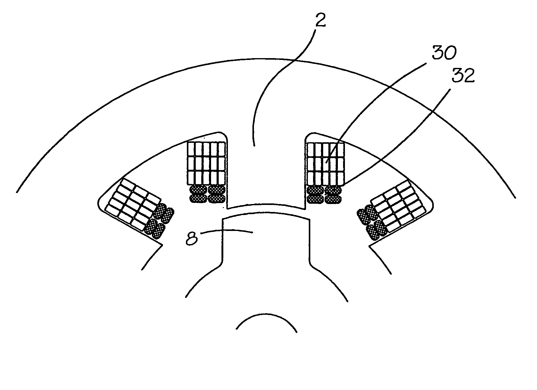
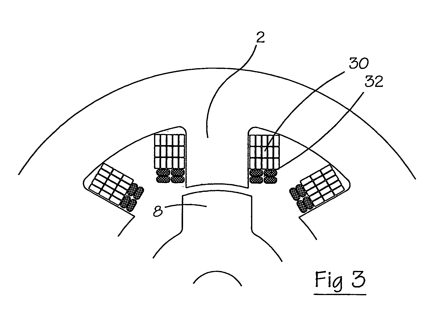
[0025]FIG. 3 shows a cross section of a coil in accordance with one embodiment of the invention. The coil, mounted on a stator pole 2, is made up from a stack of two sub-coils 30, 32. In this exemplary embodiment, the first sub-coil 30 comprises 15 turns, arranged in five layers of three turns per layer of solid rectangular strip insulated copper conductor. The second sub-coil 32 comprises four turns arranged in two layers of two turns / layer. The second sub-coil 32 is made from litz wire, for example each turn is made up of 76 strands of 0.8 mm insulated wire woven from four sub-conductors of 19 strands each, as available from wire suppliers such as Von Roll Isola of Zurich, Switzerland. As an alternative, the turns of the first sub-coil 30 can also be made up of strands. The insulation for the strands of litz wire can be a coating of, for example, magnet wire enamel. The litz wire can also be overtaped with, for example, a polyester tape or a yarn, such as nylon, silk or glass.

[00...


PUM

PropertyMeasurementUnit
areaaaaaaaaaaa
volumeaaaaaaaaaa
depthaaaaaaaaaa

Abstract

An electrical machine is provided with coils which are interconnected to form one or more windings. The coils are made up of at least two sub-coils, connected in series, the sub-coil closest to the airgap having strands in each turn which have a smaller cross sectional area than the strands in the turns in other sub-coils. This arrangement reduces the high-frequency loss in the windings while substantially minimizing any penalty associated with introducing stranding to the coil.

Description

CROSS-REFERENCE TO RELATED APPLICATION [0001] The subject matter of this application is related to the subject matter of British Patent Application No. GB 0419406.4, filed Sep. 1, 2004, priority to which is claimed under 35 U.S.C. § 119 and which is incorporated herein by reference. BACKGROUND OF THE INVENTION [0002] Embodiments of the present invention generally relate to the construction of windings for electrical machines. More particularly, embodiments of the present invention relate to the use of multi-strand windings in machines having salient poles. [0003] When a current, I, flows in the winding of an electrical machine, there is a power loss due to the resistance of the conductor. Where the resistance of the conductor, R, is measured under conditions of low- or zero-frequency, the loss is given by I2R and is called the “DC” or “zero-frequency” loss. However, when the conductor is exposed to time-varying magnetic fields, the situation is considerably more complex. Additional ...

Claims


Application Information

Patent Timeline
Patent Type & Authority Applications(United States)
IPC IPC(8): H01F21/02H02K3/20H02K19/10
CPCH02K19/103H02K3/20
Inventor RANDALL, STEVEN PAUL
Owner SWITCHED RELUCTANCE DRIVES
Why Eureka
Try Eureka