Horn antenna combining horizontal and vertical ridges

a technology of horizontal and vertical ridges and horn antennas, which is applied in the direction of antennas, waveguide horns, electrical devices, etc., can solve the problems of reducing the performance of the antenna, affecting the radiation performance of the first section, and increasing the application requirements of the application. to achieve the effect of improving the radiation characteristics of the first section

Inactive Publication Date: 2006-03-02
UNIV PUBLICA DE NAVARRA PAMPLONA
View PDF11 Cites 7 Cited by
  • Summary
  • Abstract
  • Description
  • Claims
  • Application Information

AI Technical Summary

Benefits of technology

[0013] The antenna design object of the invention comprises a second section with vertical corrugations, preferably, but not necessarily, defined according to a Gaussian profile. It is thus possible to improve the radiation features of the first section of the antenna until generating a fundamental Gaussian beam of a purity exceeding 99%.

Problems solved by technology

Currently, applications are more demanding with regard to the performances the antennas included in the telecommunication systems must comply with, whether they are land links or links via satellite.
The main drawback of the corrugated horn antennas used until today is that abrupt changes of the internal radius imply a significant reduction of the performances of the antennas.
The fact that the component has these deep corrugations at the beginning complicates the manufacturing process.

Method used


Image

  • Horn antenna combining horizontal and vertical ridges
  • Horn antenna combining horizontal and vertical ridges
  • Horn antenna combining horizontal and vertical ridges

Examples


Embodiment Construction

[0019] To see a specific embodiment of this type of antennas, the monomode circular waveguide type, starting from the fundamental mode, TE11, is focused on.

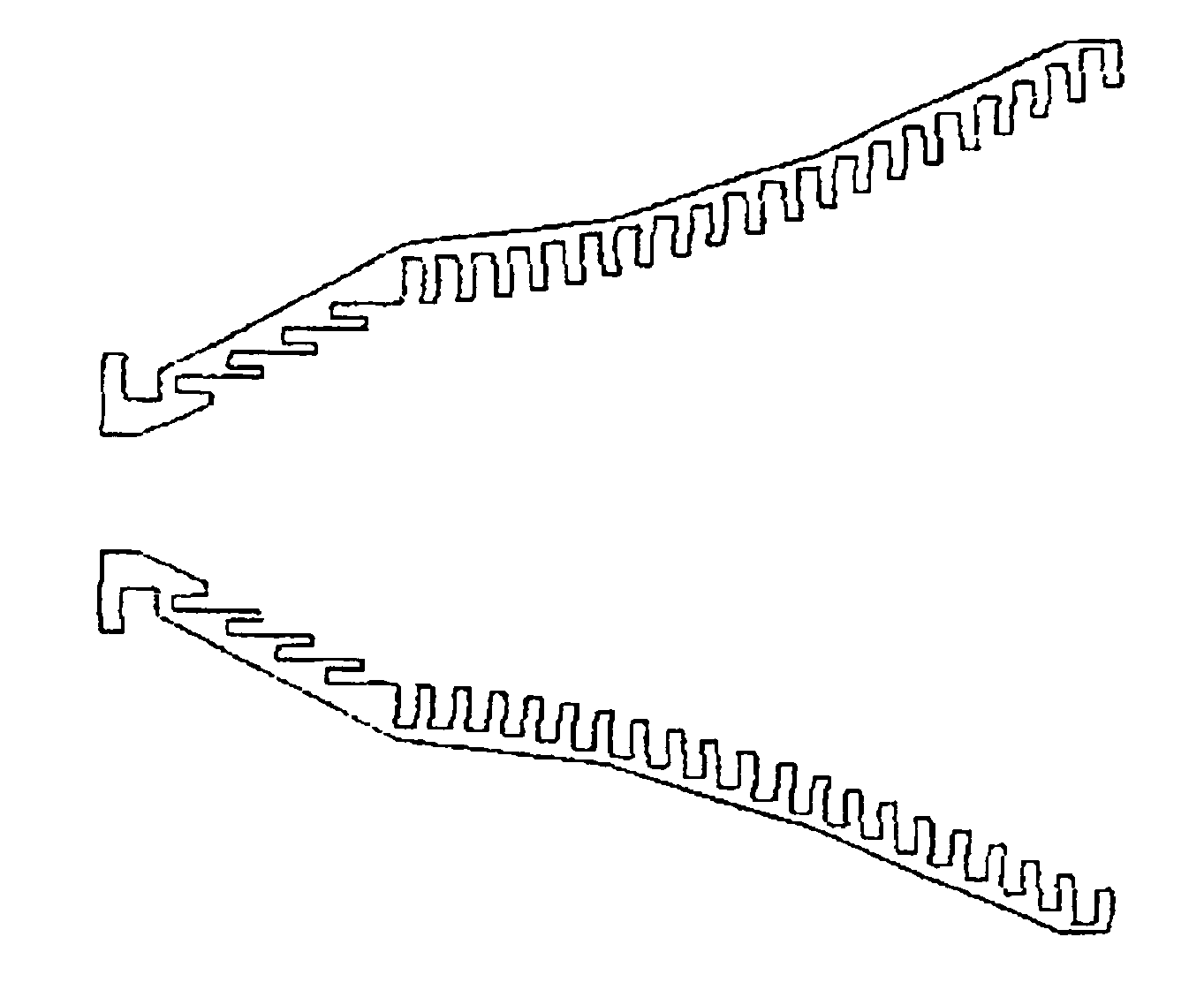
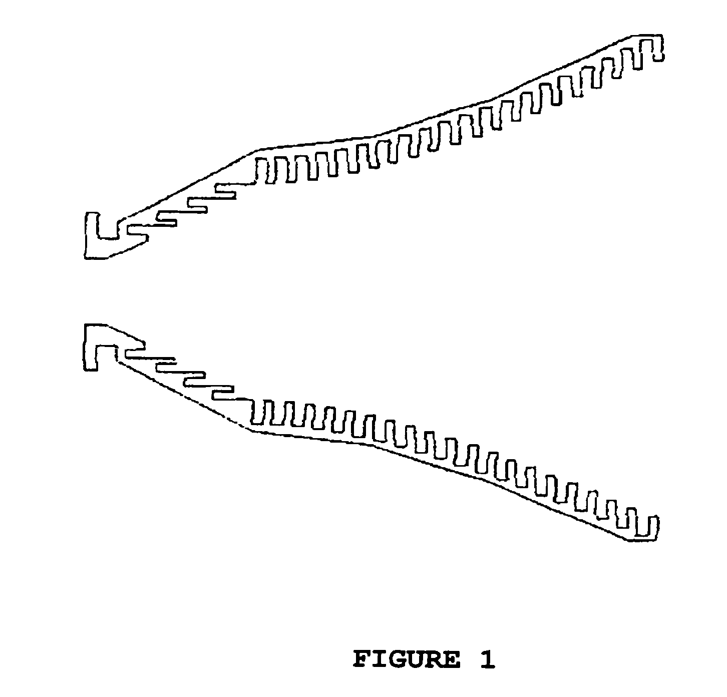
[0020] As indicated, FIG. 1 shows a cross sectional view of this type of antennas, where horizontal corrugations (corrugations parallel to the axis of propagation), in this case defined according to a line, can be seen in the first part; and a second part with vertical corrugations (corrugations transversal to the propagation) defined with, in this case, a Gaussian profile antenna section, can be seen.

[0021] The frequency of this specific design is f=9.65 GHz, and total antenna length is 194 mm (6.2 wavelengths, λ=c / f=31 mm, where c=3*10ˆ8 is the speed of light in free space). The aperture radius is 11.7 mm, and the output radius is 81.2 mm.

[0022] The horizontal corrugations have a 5 mm period with a 2 mm tooth width and 7 mm depth. The vertical corrugations have a 7 mm period, a 3 mm tooth width and 8.8 mm depth.

[0023] The f...


PUM


Abstract

A horn antenna combining horizontal and vertical corrugations. It is made up of two well differentiated parts, the first part being an antenna with horizontal corrugations, i.e. parallel to the axis of propagation, and a second part with vertical corrugations, i.e. transverse to the axis of propagation. The aperture of the arrangement of the corrugations, in the two parts, can preferably follow linear or Gaussian functions.

Description

SECTOR OF THE ART TO WHICH INVENTION REFERS [0001] The component presented is encompassed within electromagnetic systems for guiding energy at millimeter wave and microwave frequencies, and optimally adapts any electromagnetic field structure present inside a waveguide with a Gaussian structure. PRIOR STATE OF THE ART [0002] Currently, applications are more demanding with regard to the performances the antennas included in the telecommunication systems must comply with, whether they are land links or links via satellite. [0003] Smaller and smaller levels of side lobes are required, since, in short, they imply an effective loss of power in the desired radiation direction. At the same time, and due to the large demand of services, it becomes necessary to reuse frequencies using polarization diversity to differentiate two signals. This fact generates a great interest in having very low cross polarization levels, which, in short, is the measure of isolation between these two possible si...

Claims


Application Information

Patent Timeline
Patent Type & Authority Applications(United States)
IPC IPC(8): H01Q13/00H01Q13/02
CPCH01Q13/0216H01Q13/0208
Inventor DEL RIO BOCIO, CARLOSGONZALO GARCIA, RAMONGONI CAMPAIN, DAVIDTENIENTE VALLINAS, JORGE
Owner UNIV PUBLICA DE NAVARRA PAMPLONA
Why Eureka
Try Eureka