

Optical element and image taking apparatus
a technology which is applied in the field of optical elements and image taking apparatus, can solve the problems of deteriorating lens performance, aqueous solution being decomposed, and the inability to freely change the refractive index of the lens, so as to reduce the deterioration of performance
- Summary
- Abstract
- Description
- Claims
- Application Information
AI Technical Summary
Benefits of technology
Problems solved by technology
Method used
Image

Examples
first embodiment
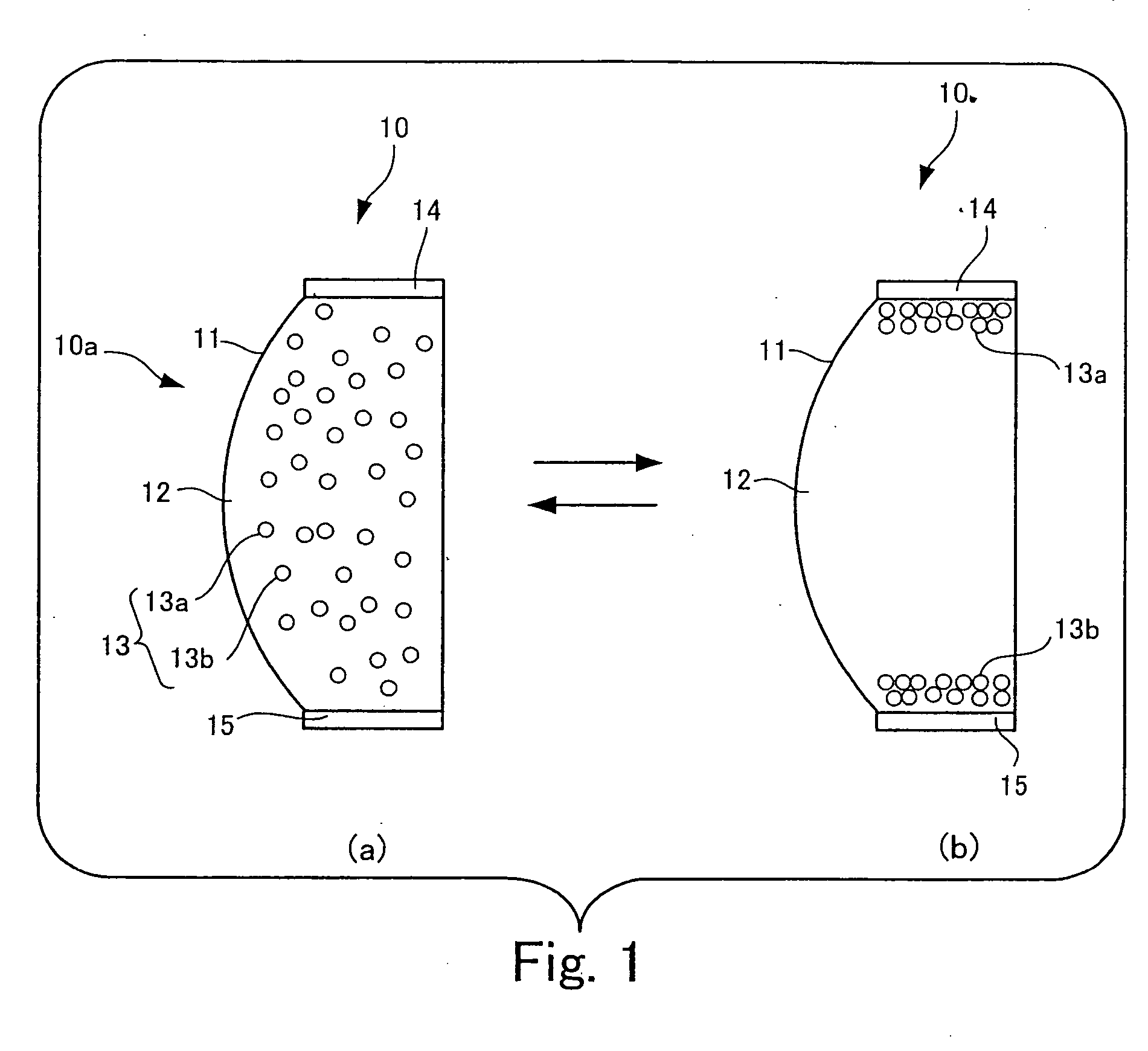
[0105]FIG. 1 is a diagram showing a sectional configuration of a variable-focus lens which is the optical element of the present invention.
[0106] The variable-focus lens 10 shown in part (a) and part (b) of FIG. 1 has a container 11 which is light-transmissive at least in a light passage region 10a, and which has the shape of a lens. The container 11 corresponds to an example of the container according to the present invention. At least the light passage region 10a of the container 11 has the shape of a lens having a convex outer surface.
[0107] In the variable-focus lens 10, a light-transmissive dispersion medium 12 enclosed in the container 11 is provided. The dispersion medium 12 is an example of the dispersion medium in accordance with the present invention.
[0108] In the variable-focus lens 10, a dispersoid 13 is also provided which is dispersed in the dispersion medium 12, which is light-transmissive, and which has a refractive index higher than that of the dispersion medium 1...
second embodiment
[0186]FIG. 6 is a diagram showing a sectional configuration of a variable-focus lens 20 which is the optical element of the present invention.
[0187] The same components as those of the variable-focus lens 10 shown in FIG. 1 are indicated by the same reference characters. Description will be made of points of difference from the variable-focus lens 10 shown in FIG. 1.
[0188] The variable-focus lens 20 shown in FIG. 6 differs from the variable-focus lens 10 shown in FIG. 1 in that each of the inner surfaces of the cathode 14 and the anode 15 is coated with insulating film 24 which is placed adjacent to the dispersion medium 12. In this variable-focus lens 20, the insulating film 24 provided as a coating on the inner surfaces of the cathode 14 and the anode 15 prevents agglomeration of the dispersoid 13 on the cathode 14 and the anode 15. The insulating film 24 is a polyimide insulating film. Therefore, the cathode 14 and the anode 15 have excellent heat resistance and durability. In t...
third embodiment
[0189]FIG. 7 is a diagram showing a sectional configuration of a variable-focus lens which is the optical element of the present invention.
[0190] The same components as those of the variable-focus lens 20 shown in FIG. 6 are indicated by the same reference characters. Description will be made of points of difference from the variable-focus lens 20 shown in FIG. 6.
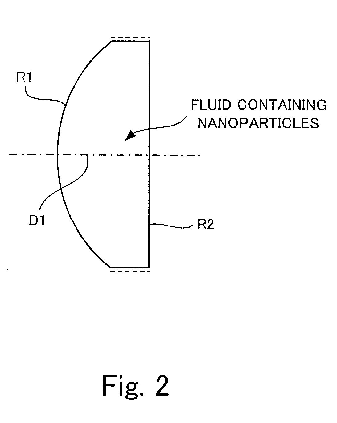
[0191] The variable-focus lens 30 shown in FIG. 7 has a container 31 which is light-transmissive at least in a light passage region 10a, and which has the shape of a lens. At least a portion of the container 31 in the light passage region 10a is formed of a plastic. Therefore, the container 31 can be realized as a lightweight container having high impact resistance. In the variable-focus lens 30 having the thus-formed container 31, the refraction of light passing through the light passage region 10a may be controlled through electrophoresis of the dispersoid 13. The container 31 may be formed of glass instead of being form...
PUM
 Abstract
Description
Claims
Application Information