Lens-positioning device of camera module

a technology of lens positioning and camera module, which is applied in the field of lens positioning device of camera module, can solve the problems of inconvenient installation of conventional cameras on small sized mobile phones, limited sharpness of images, and difficulty in providing accurate control of lens positioning for performing accurate focusing. , to achieve the effect of accurate positioning of lenses, simple construction and minimal siz

Inactive Publication Date: 2006-03-02
SAMSUNG ELECTRO MECHANICS CO LTD
View PDF7 Cites 49 Cited by
  • Summary
  • Abstract
  • Description
  • Claims
  • Application Information

AI Technical Summary

Benefits of technology

[0023] The present invention has been made to solve the above problems, and it is an object of the present invention to provide a lens-positioning device of a camera module, designed to have a miniaturized size and simple construction, and to allow accurate positioning of the lens.

Problems solved by technology

However, in such a fixed focus manner, since it is impossible to set focus to a specific distance from an object, there is a problem in that sharpness of an image is limited.
However, it is not appropriate to install the conventional camera on the small sized mobile phone.
As a result, it is difficult not only to provide accurate control of positioning of the lens for performing accurate focusing due to reduction of a response speed and variation of a rotational velocity, but also to realize the focusing within an extremely limited space in the mobile phone due to its complicated structure and large volume.
In such a manner, the lens is not automatically moved, and thus, although this manner can be applied to the optical zoom function, it cannot be applied to the focusing.
Accordingly, with the construction as shown in FIG. 2, it is very difficult to minutely adjust focal length by manually rotating the zoom lens case 250.
Additionally, with the construction as described above, the zoom lens 210 is rotated, resulting in change of an optical axis, whereby high resolution cannot be accomplished.
As a result, the problem of enlarging the volume of the camera module cannot be basically solved, and thus, this construction is not appropriate for a miniaturized optical device, which must be driven within an extremely restricted space.

Method used


Image

  • Lens-positioning device of camera module
  • Lens-positioning device of camera module
  • Lens-positioning device of camera module

Examples


Embodiment Construction

[0040] Embodiments of the present invention will be described in detail with reference to the accompanying drawings.

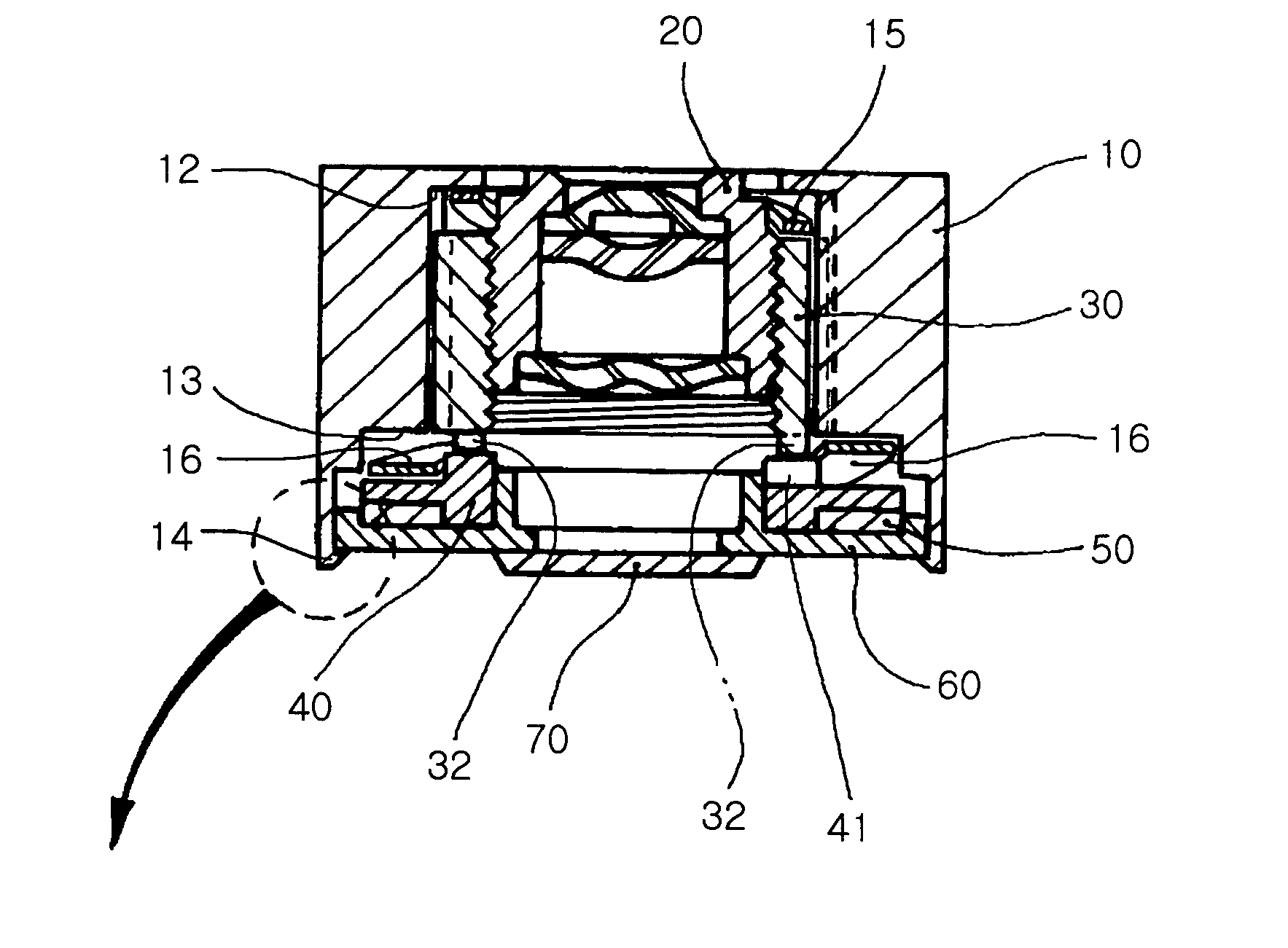
[0041]FIG. 4 is a perspective view illustrating an essential component of a lens-positioning device according to the present invention, and FIGS. 5a to 5c are cross-sectional views illustrating the central portion of the lens-positioning device of the present invention.

[0042] Referring to FIG. 4, a lens-positioning device of a camera module according to the present invention comprises an actuating part 300, a positioning part 400, and a housing 10, which receives the actuating part 300 and the positioning part 400.

[0043] The actuating part 300 includes a ring-shaped piezoelectric actuator 50, which generates a mechanical actuating force in response to a voltage applied to the piezoelectric actuator 50, and a rotating plate 40 positioned on an upper surface of the piezoelectric actuator 50 to be rotated around an optical axis of at least one lens in response to the a...


PUM


Abstract

A lens-positioning device of a camera module designed to provide a focusing function or an optical zoom function. In the lens-positioning device, an actuating part includes a ring-shaped piezoelectric actuator and a rotating plate positioned on an upper surface of the piezoelectric actuator. A positioning part is provided with a hollow barrel holder and linearly moved in the direction of the optical axis of the lens upon rotation of the rotating plate. The hollow barrel holder contacts the upper surface of the rotating plate. A hollow housing receives the actuating part and the positioning part and having a guide means to guide the positioning part to be linearly moved in the direction of the optical axis of the lens. The lens-positioning device can have ultra-miniaturized size through the piezoelectric actuator, and a minute focusing can be realized through minute positioning of the lens, allowing high resolution and high sharpness images.

Description

RELATED APPLICATION [0001] The present application is based on, and claims priority from, Korean Application Number 2004-0069985, filed Sep. 2, 2004, the disclosure of which is hereby incorporated by reference herein in its entirety. BACKGROUND OF THE INVENTION [0002] 1. Field of the Invention [0003] The present invention relates to a lens-positioning device of a camera module, and more particularly to a lens-positioning device of a camera module, designed to convert rotational movement of a rotating plate with an actuating force by a traveling wave generated by a piezoelectric actuator to linear movement of the lens, thereby allowing focusing function and providing a close-up or optical zoom function. [0004] 2. Description of the Related Art [0005] Generally, a camera comprises a plurality of lenses, and is constructed such that the optical focal length can be adjusted by changing relative distances between the lenses by moving respective lenses. Recently, mobile phones with a came...

Claims


Application Information

Patent Timeline
Patent Type & Authority Applications(United States)
IPC IPC(8): H04N5/225
CPCG02B7/102H04N5/2257H04N5/2254H04N23/57G02B13/009
Inventor KIM, OUI SERGCHANG, IN BAEKOC, BURHANETTINJEONG, DAE HYUNKIM, WOON KIRYU, JUNG HO
Owner SAMSUNG ELECTRO MECHANICS CO LTD
Why Eureka
Try Eureka