

Image reading apparatus
a technology for reading apparatus and document plates, applied in the direction of electrical apparatus, picture communication, etc., can solve the problems of high manufacturing cost, unfit for a reduction in size, and the image reading apparatus cannot clearly read a document placed at a position, so as to achieve the effect of not increasing the size of the document pla
- Summary
- Abstract
- Description
- Claims
- Application Information
AI Technical Summary
Benefits of technology
Problems solved by technology
Method used
Image

Examples
first embodiment
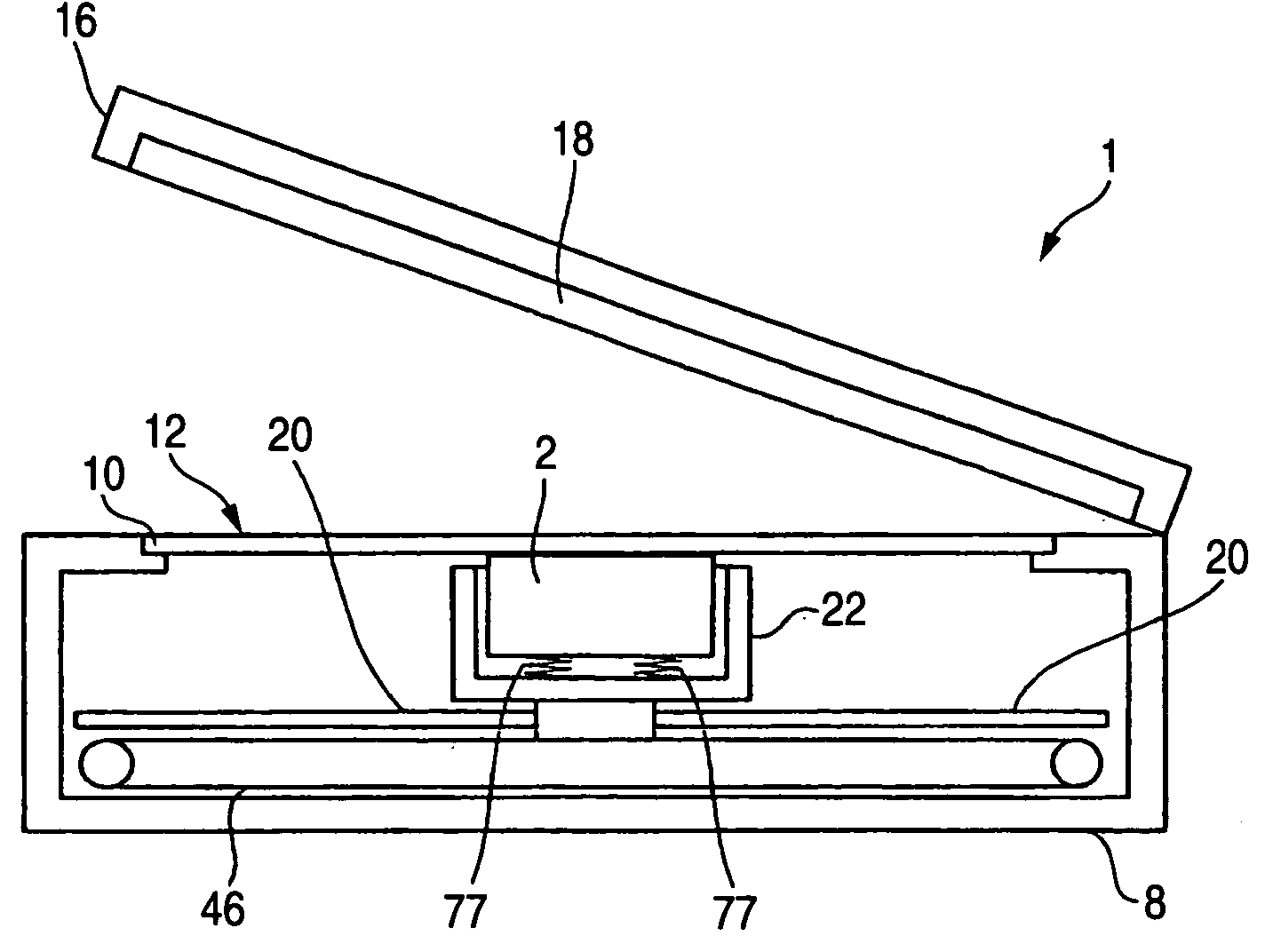
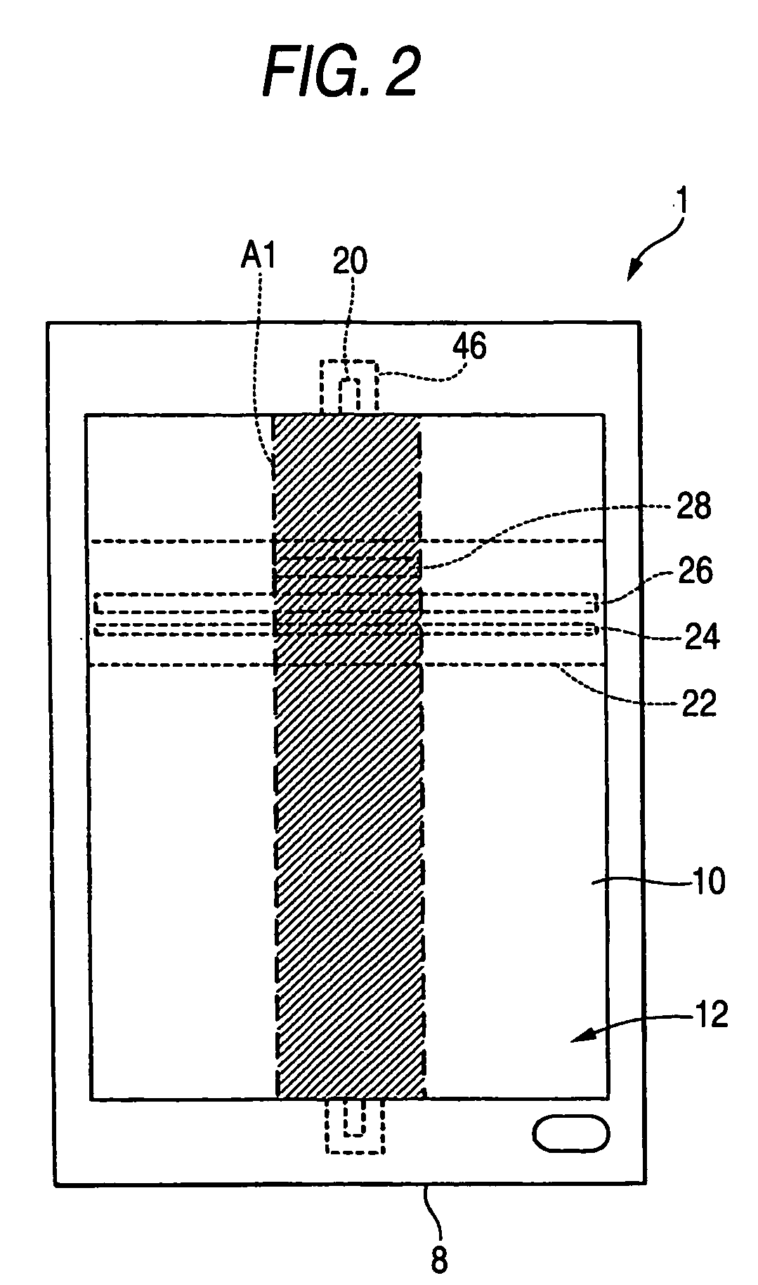
[0051] FIGS. 2 to 4B are schematic views of an image scanner 1 serving as an image reading apparatus of a first embodiment of the invention. The image scanner 1 is a so-called flat-bed type image scanner. The image scanner 1 can read a reflective document 4 (see FIG. 4A) of up to A4 size and A4 / letter size and a transmissive document. The reflective document 4 is a printed document, a photograph, or the like. The transmissive document is a 35 mm film (negative / positive) 6 (see FIG. 4B) or the like. In the following description, the 35 mm film is used as the transmissive document. Additionally, the image reading apparatus may be a sheet-feed type image scanner and may also be a complex machine. Besides, the transmissive document is not limited to the 35 mm film.
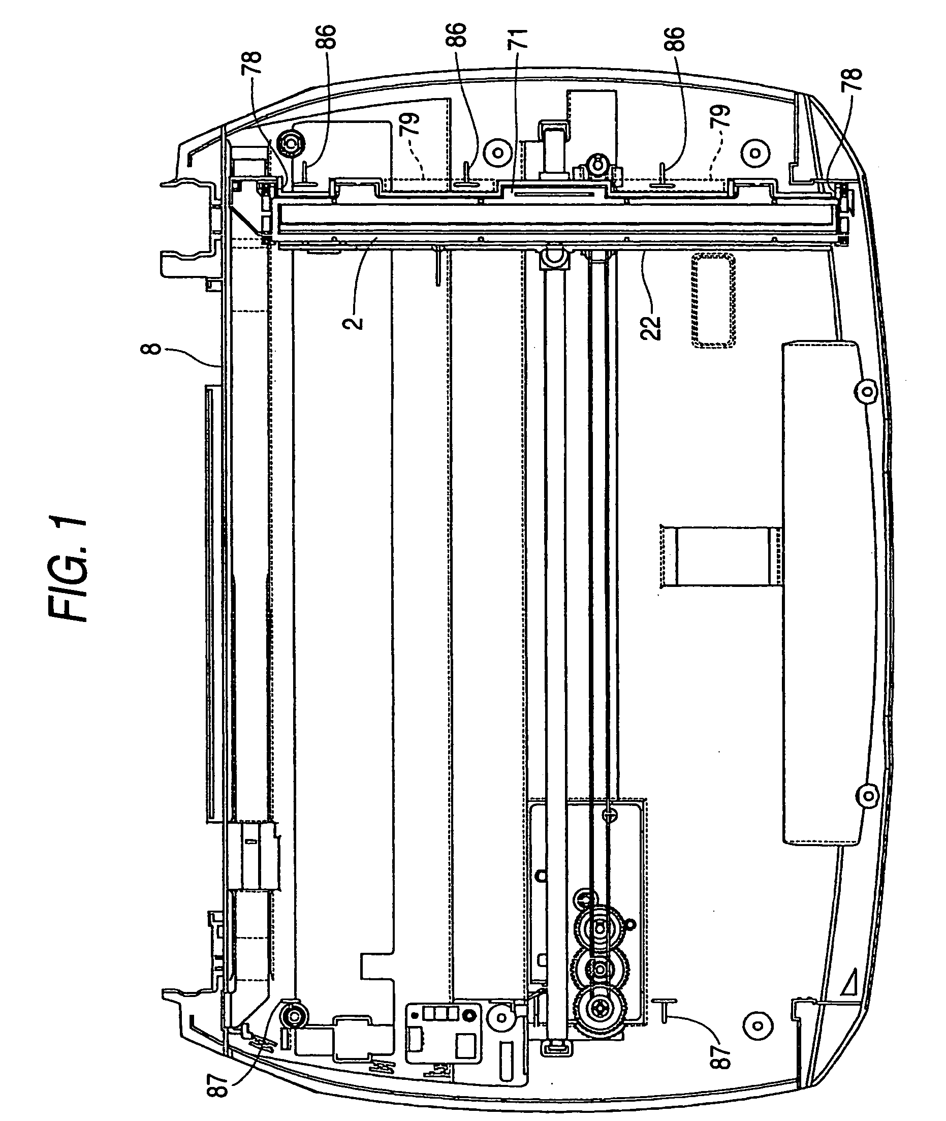
[0052] A housing 8 shown in FIG. 3 is formed into an open-topped box shape. A document platen 10, formed of a substantially rectangular transparent plate such as a glass plate, closes an opening of the housing 8. The reflecti...
second embodiment
[0093]FIG. 14A is a top view of a contact image sensor module 90 of a second embodiment, and FIGS. 14B and 14C are side views of the contact image sensor module 90 as seen from the directions X and Y, respectively, shown in FIG. 14A. In the second embodiment as well, a second linear image sensor 32 is housed in a first protruding portion 91 of a casing 99, and a first linear image sensor 30 is housed in a portion other than the first protruding portion 91. As shown in the figure, in the second embodiment, the first protruding portion 91 is provided not at a main scanning-direction center, but at a position offset from the center. The position of the supports 86 is taken up in the vicinity of the center of the contact image sensor module 90 in the main scanning direction, the first protruding portion 91 is displaced as shown in the figure, whereby the supports 86 can be prevented from abutting the first protruding portion 91. The first protruding portion 91 may be provided thus appro...
third embodiment
[0094]FIG. 15 is a schematic view of a contact image sensor module 2 of a fifth embodiment. FIG. 15 is a schematic view thereof as seen from the longitudinal direction of a first linear image sensor 30 and, at the same time, a schematic view thereof as seen from the longitudinal direction of a second linear image sensor 32. Here, the direction X in the figure indicates the sub scanning direction. A spacer of the fifth embodiment is divided into a first spacer 110 and a second spacer 111. When the contact image sensor module 2 is seen from the longitudinal direction of the first linear image sensor 30, as shown in the figure, a projection 112 of the first spacer 110 is provided so as to be positioned on a centerline 114 of rod lenses 36. When the projection 112 is positioned on the centerline 114 of the rod lenses 36, the height of the projection 112 can also be made equal to the distance between the rod lenses 36 and the document platen 10. Consequently, when the distance between th...
PUM
 Abstract
Description
Claims
Application Information