Write pole and method of manufacturing the same

a technology of writing pole and manufacturing method, which is applied in the direction of head surface, instruments, and heads with metal sheet cores, etc., can solve the problems of reducing the field gradient of adjacent tracks, affecting the planarity of the trailing edge of the write pole, and utilizing conventional methods of fabrication, such as ion milling, to achieve the effect of reducing the interference of adjacent tracks, and aggravating the flare-point throa

Inactive Publication Date: 2006-03-02
WESTERN DIGITAL TECH INC
View PDF16 Cites 79 Cited by
  • Summary
  • Abstract
  • Description
  • Claims
  • Application Information

AI Technical Summary

Benefits of technology

[0007] Embodiments of the present invention are directed toward a write head for generating an improved flux field while minimizing adjacent track interference (ATI) and a manufacturable method of constructing the same. In one embodiment, a method of fabricating a magnetic write head includes forming a beveled write pole. A conformal spacer may be formed upon a portion of a flare length proximate a tip of the write pole. A shield layer may also be formed upon the conformal spacer adjacent the flare length proximate the tip of the write pole.
[0010] Embodiments of the present invention provide a single-pole write head including a beveled write pole with a leading edge tapering and / or an aggressive flare-point throat height. The single-pole write head may also include a self-aligned side and trailing shield. The beveled write pole and / or write pole with a self-aligned side and trailing edge shield is adapted to generate a flux field for perpendicular recoding at densities between approximately 1 gigabit per square inch and 1 terabit per square inch or more. The flux field has an improved field gradient for minimizing adjacent track interference. Embodiments of the invention also provide a manufacturable method of constructing the write head.

Problems solved by technology

Simultaneously controlling the flare point and control the track-width of the write pole, utilizing conventional methods of fabrication, such as ion milling, is problematic.
Thus, reducing the width and / or length of the write pole tip may create a magnetic field adjacent to the bit but outside of the track in which the writing process is taking place, thereby corrupting the bits on adjacent tracks.
Similarly, it becomes more difficult to simultaneously maintain the planarity of the trailing edge of the write pole as the width and / or length is decreased using an ion mill approach.
A reduction in the quality of the trailing edge may reduce the quality of the linear transition between each bit.

Method used


Image

  • Write pole and method of manufacturing the same
  • Write pole and method of manufacturing the same
  • Write pole and method of manufacturing the same

Examples


Embodiment Construction

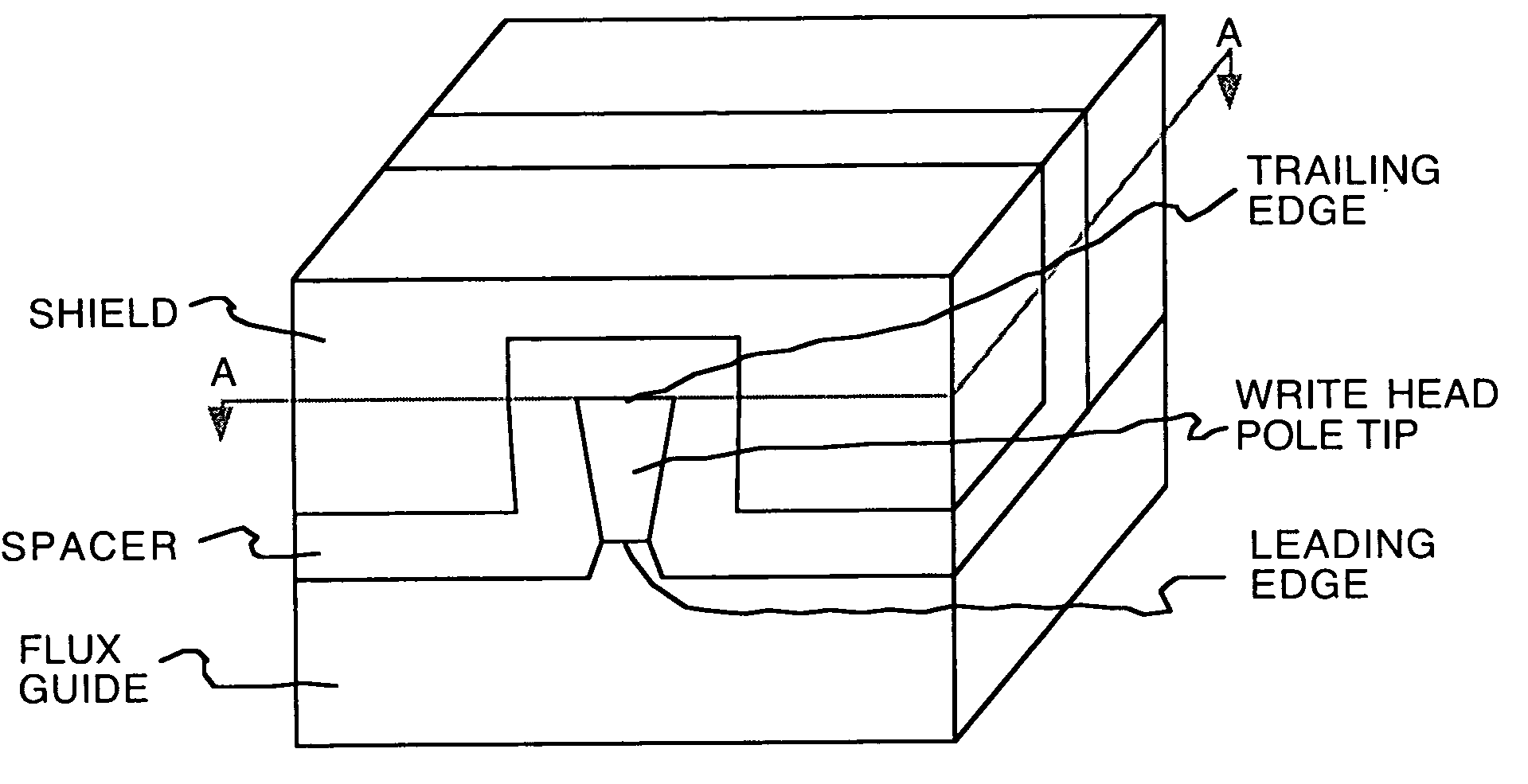
[0017] Reference will now be made in detail to the embodiments of the invention, examples of which are illustrated in the accompanying drawings. While the invention will be described in conjunction with these embodiments, it will be understood that they are not intended to limit the invention to these embodiments. On the contrary, the invention is intended to cover alternatives, modifications and equivalents, which may be included within the scope of the invention as defined by the appended claims. Furthermore, in the following detailed description of the invention, numerous specific details are set forth in order to provide a thorough understanding of the present invention. However, it is understood that the invention may be practiced without these specific details. In other instances, well-known methods, procedures, components, and circuits have not been described in detail as not to unnecessarily obscure aspects of the invention. For example, it is appreciated that the write head...


PUM

PropertyMeasurementUnit
thicknessaaaaaaaaaa
angleaaaaaaaaaa
thicknessaaaaaaaaaa

Abstract

A magnetic write head and method of fabrication, in accordance with one embodiment of the present invention, includes depositing a first hard mask layer on a layer of magnetic material, depositing a second hard mask layer on the first hard mask layer, depositing a third hard mask layer on the second hard mask layer and forming a soft mask upon the third hard mask layer defining a write pole. The third hard mask layer exposed by the soft mask is etched utilizing a first chemistry, wherein the pattern of the write pole is transferred from the soft mask to the third hard mask. The second and first hard mask layers exposed by the patterned third hard mask are etched utilizing a second chemistry thereby forming a first and second hard mask. The selectivity of the second chemistry favors the first and second hard mask layers over the third hard mask. The layer of magnetic material exposed by the first hard mask is milled such that a beveled write pole is formed. The selectivity of the milling favors the magnetic material over the first hard mask

Description

BACKGROUND OF THE INVENTION [0001] Magnetic heads are used in disk drives to write information on to a moving magnetic media and to read the information stored thereon. Conventional magnetic heads include a write head and a read head. A write head should be capable of writing straight and sharp transitions. The write head should also be capable of writing the data on a given track without reducing the signal of adjacent or nearby tracks. [0002] The write head may implement a longitudinal recording mode or a perpendicular recording mode for magnetically encoding data on a disk. A longitudinal write head, in accordance with the conventional art, is depicted in FIG. 1A. In longitudinal recording, a coil 105 wound around a toroid 110 generates a magnetic flux. The fringe field 115 proximate a gap in the toroid 110 causes orientation of a magnetic recording layer 120, having a horizontally orientated magnetic domain, on a disk as a function of the current through the coil 105. [0003] A p...

Claims


Application Information

Patent Timeline
Patent Type & Authority Applications(United States)
IPC IPC(8): G11B5/127G11B5/23
CPCG11B5/1278G11B5/1475G11B5/315Y10T29/49046Y10T29/49041Y10T29/49043G11B5/3163
Inventor LE, QUANGZOLLA, HOWARDSUN, NIAN-XIANG
Owner WESTERN DIGITAL TECH INC
Why Eureka
Try Eureka