Buffered magazine method and system for loading and unloading ships

Inactive Publication Date: 2006-03-02
HUBBARD WILLIAM B SR
9 Cites 37 Cited by

AI-Extracted Technical Summary

Problems solved by technology

Delay to the vessel is arguably the most expensive component of a cargo transportation system.
However, as ship capacity grew, the warehouses or sheds disappeared and the containers were marshaled in large parking lots near the pier waiting for the ship's arrival.
The disadvantage of these large terminals is that land available in port areas is scarce and very expensive.
In addition to the scarcity and expense of the resources, the ability to develop available land has become suspect.
Environmental concerns virtually preclude significant reclamation from wetlands in the future, thus threatening the ability to develop the available port area land for adequate storage capacity.
Exacerbating the problem is the fact that existing facilities are nearly at capacity in many areas; some approaching gridlock.
Despite the impending need, no working solutions have been discovered...

Method used

[0097] The container ship 41 will maintain its SLD operation of each hatch until all import containers 56, 58 have been discharged. At this point, the process will convert to a load only operation until all the remaining export containers 47, 48, have been loaded. The final containers loaded onto the container ship will come from containers in the ITZ 79, FIG. 5. At this stage, the last of the well cars 49 will have been loaded and have departed, and the train operations will have terminated, thus leaving the dock clear of containers 55. Thereafter, the rail magazine can be used by another container ship immediately, thus greatly increasing the efficient use of space. The efficiency of the invention thus described is dependent on whe...

Benefits of technology

[0024] Another advantage of the present invention is that it utilizes a method of integrating the simultaneous load and discharge of a container ship with the simultaneous load and discharge of a stack train. In the preferred embodiment, the simultaneous load and discharge of both vessel and train are maximized.
[0025] Another advantage of the invention is that it permits cargo storage areas to be moved away from the ship and relocated to an area where land is more available.
[0026] Another advantage of the invention is that it permits the interfacing of vessels and rail cars with a high degree of timing and reliability.
[0027] Another advantage of the invention is that it minimizes or eliminates local traffic problems and residents' objections associated with port related traffic.
[0028] Another advantage of the invention is that trains could originate and terminate at the port complex with lit...

Abstract

An buffered marine magazine terminal method provides for the discharge of import containers from a container ship to well cars, in the simultaneous discharge of export containers from well cars to an ITZ. Once the container ship is sufficiently unloaded, export containers from the ITZ may be loaded onto the container ship using a double-buffered magazine method and system. Simultaneously, the ship may be discharged of further import containers. The method also provides for reworking of well cars at a remote rail buffer and classification yard, in communication between the intermodal interface center and the remote rail buffer and classification yard via a dedicated freight corridor. A data management system manages the intermodal exchange of containers between ship, rail, and truck utilizing a common user electronic data management system.

Application Domain

Technology Topic

Image

  • Buffered magazine method and system for loading and unloading ships
  • Buffered magazine method and system for loading and unloading ships
  • Buffered magazine method and system for loading and unloading ships

Examples

  • Experimental program(1)

Example

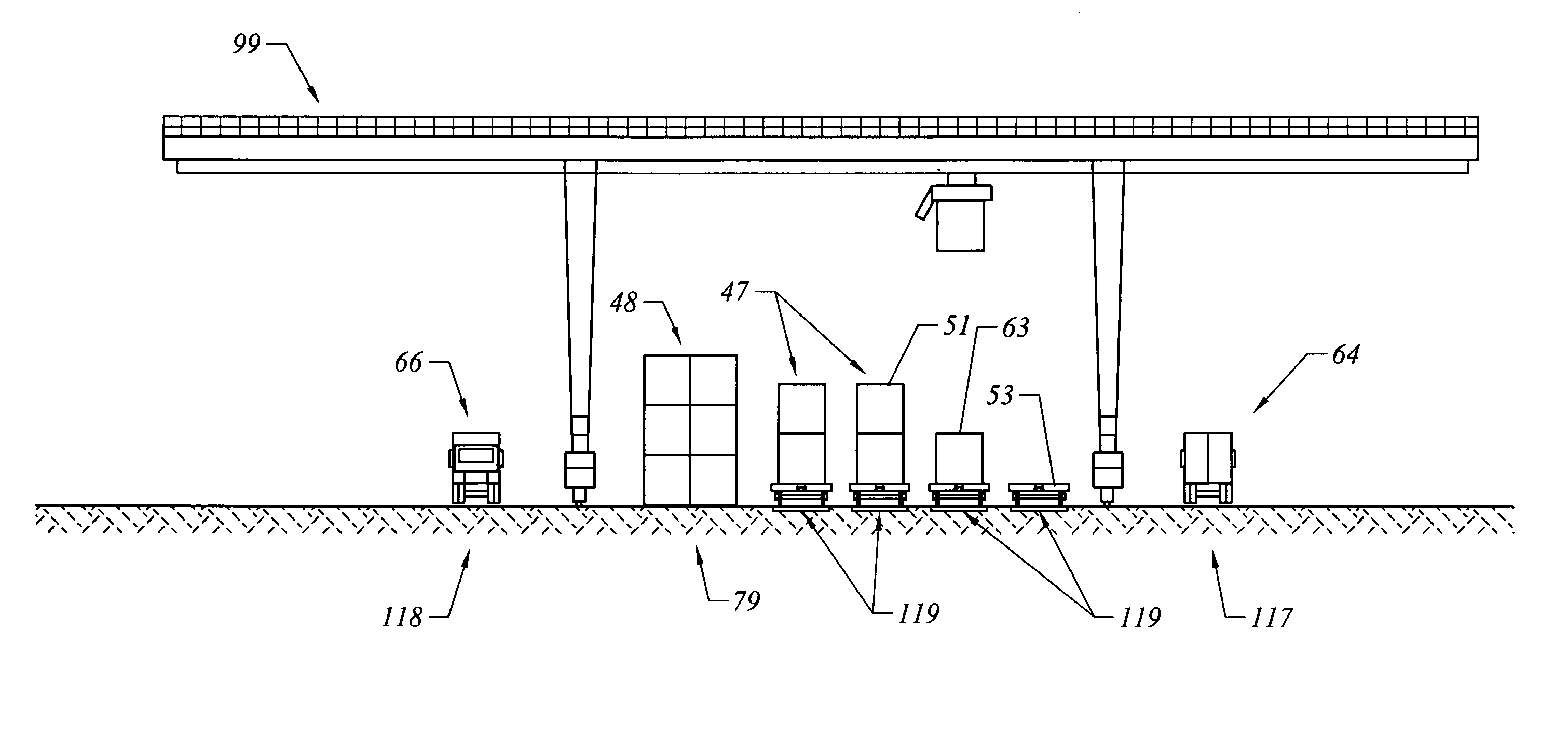
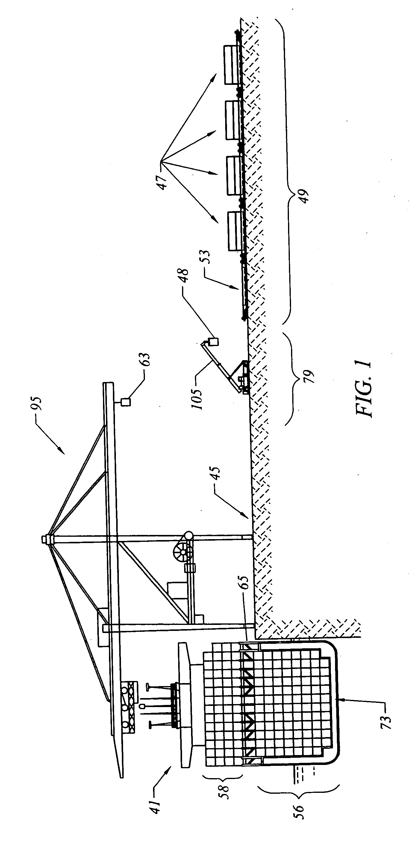
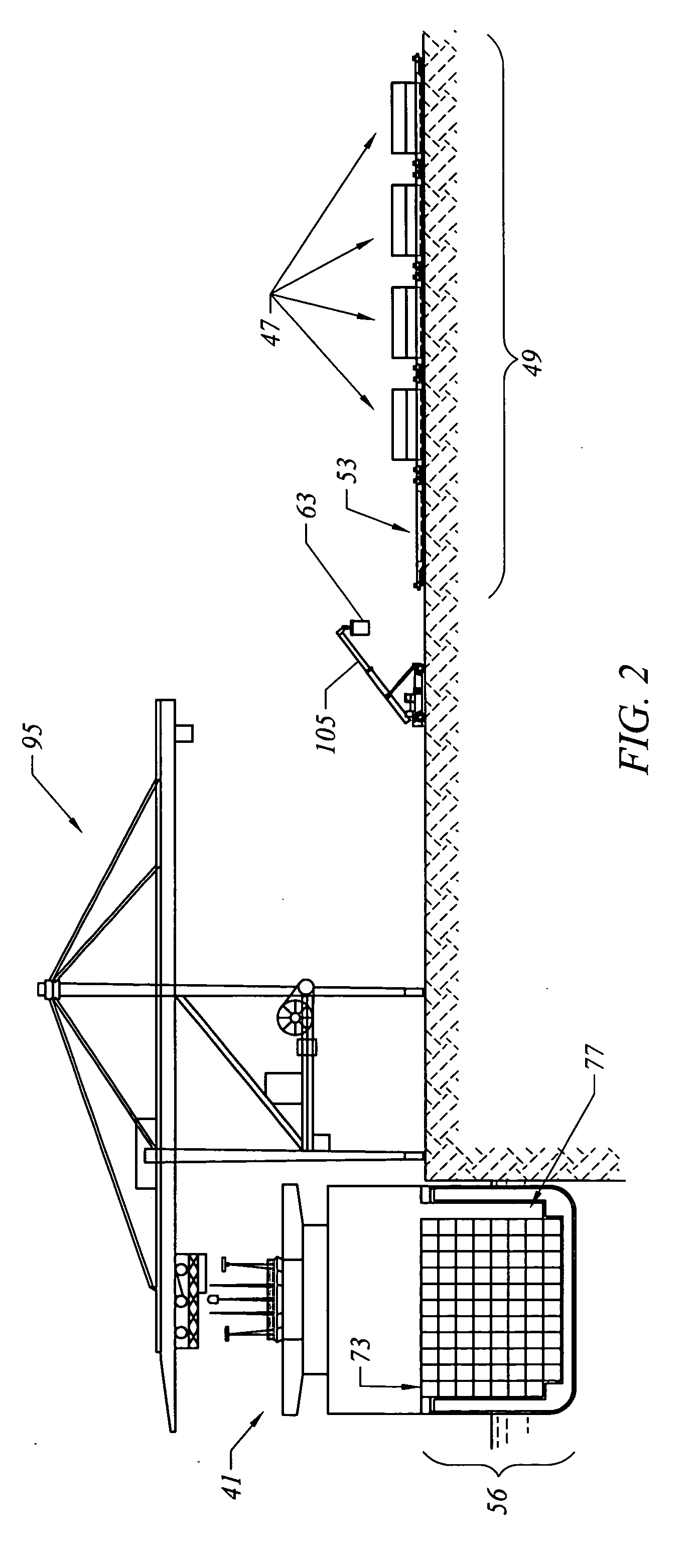
[0085] In FIG. 1, consider the following example of the above operation. At the start of operations, a container ship 41 arrives full of import cargo, including containers 58 stored in the on-deck stow and containers 56 stored in the below deck stow. There are some export containers 47, 48 on well cars 49.
[0086] The on-deck stow 58 is cleared with the crane 95, onto the pier 45. Each container 63 is picked up by the mobile lift 97, 105 from the pier 45 and transported to the rail magazine 121, where it is placed in a well car 49, 53. Meanwhile, export containers 47, 48 are removed from the well car 49 and placed in the ITZ 79. This process is repeated until the on-deck stow 58 is clear, hatch covers 65 have been removed, below deck containers 56 have been removed, and there is a cleared vertical cell 77. The containers that were in the on-deck stow 58 of the container ship 41 are now on the well cars 49. The export containers that were on the well cars 49 are now in the ITZ 79 or still loaded in well cars 53.
[0087] Thus, the operation as thus far described begins with a one-way discharge of import containers 58 from the container ship 41 and a simultaneous discharge and load of well cars 49 destined for the ITZ 79. Export containers 47, 48 are removed from a well car 49 and immediately replaced with import containers 56, 58, 63 just discharged from the container ship 41.
[0088] The ship maintains a discharge only operation until the on-deck stow 58 has been cleared, the hatch covers 65 removed, and a cleared vertical cell 77 has been created (FIG. 2). At this point, an inventory of ITZ 79, FIG. 5 containers 48, FIG. 5 for export is accumulated in the ITZ 79, the number of these containers being approximately equal to the number of containers from the container ship 41 that have been discharged.
[0089] The process continues as follows. Containers 56 and 58 continue to be taken from the container ship 41 by the crane 95, placed on the pier 45, and transported by the mobile lift 97, 105 to the rail magazine 121 where each import container is loaded onto a well car 49, 51, 53. The export containers 47 and 48 (FIG. 5) or 47 (FIG. 1) from the well cars 49 are transported by another mobile lift 97, 105 to either the container ship 41 or the ITZ 79. Whether the container is taken directly to the ship 41 or the ITZ 79 depends on the container's attributes, keeping in mind that containers should be loaded on the ship 41 as customarily determined by their attributes. Attributes considered may include destination, weight, hazardous materials, temperature-controlled cargo, and container size.
[0090] The selection of containers 55 to be loaded onto the well cars 49 and thence to the train is accomplished in a different way. Ideally, only short blocks of well cars 49 would be unloaded/loaded at the rail magazine 121. The container ship 41 was loaded at its origin to ensure that containers for priority destinations are concentrated in the on-deck stow 58 and in the vertical cell 73 which will become the first cleared vertical cell 77. As the initial well cars 49 are loaded with import loads, they can be shuttled to a RRBCY 113 where they can be combined with other rail cars until sufficient cars have been accumulated to form a train that is destination specific or sent to the IIC 91. At the IIC 91, the rail cars from the BMMT could combine with cars with containers from other container ships or rail cars containing containers with domestic cargo.
[0091] Once the container ship 4t commences this simultaneous load and discharge mode, an export container 47 can be loaded onto the container ship 41 as a new import container 63 is discharged from the container ship 41. Specifically, the crane 95 discharges an import container 63 from a next vertical cell 73 to be cleared onto the pier 45. The mobile lift 97, 105 has, meanwhile, placed an export container on the pier 45. Then, the crane 95 loads the export container into the cleared vertical cell 77.
[0092] Export containers 47, 48 can be loaded directly from the well car 49 into the container ship 41 or the ITZ 48. If the container 47, 48 does not have the proper attributes to be loaded at the time, it may be stored in the ITZ 79, and replaced with an ITZ container 48 that does meet the loading requirements at the time, and thus be loaded onto the container ship 41. This particular stowing protocol can be maintained without any increase in the inventory of ITZ containers 48 contained within the ITZ 79, as one replaces the other.
[0093] The simultaneous load and discharge process continues until all of the import containers 56, 58, 63 have been discharged from the particular hatch. The container ship 41 now commences a load only operation until the last vertical cell 73 is filled, the hatch covers 65 replaced, and the on-deck stow 58 is loaded with export containers.
[0094] The integrated simultaneous load and discharge of both the container ship 41 and the train can be maintained indefinitely as long as well cars 49 in rail magazines 121 are supplied and removed “just in time” to maintain the operation. The significance is that a ship of any size can be worked without a further increase in the size of the yard, assuming the same number of cranes are used. It would take longer to work a larger ship than a smaller ship, but would not require any more land for the operation.
[0095] The only containers required to be inventoried on a dock at the site is that number of export containers discharged from the train that could not be loaded onto the container ship, until the container ship 41 could institute a SLD mode of operation. The largest known ships today would require an inventory of a maximum of 105 containers for the largest hatches. It is anticipated that this number may increase in the future. The inventory of ITZ containers 48 is required to be maintained in the ITZ 79 only during the time those hatches are actually being worked. The recommended maximum inventory in the ITZ 79 of a rail magazine 121 at any given time is therefore the sum of the number of containers in the on-deck stow of the hatch and the number of containers needed to clear one of the largest vertical cells, which is a requirement to institute an SLD operation.
[0096] Once the first two containers 47 have been discharged from a well car 49, a simultaneous load and discharge operation can be commenced until the final two export containers 47 have been discharged and the final import containers 63 loaded onto the well cars 49.
[0097] The container ship 41 will maintain its SLD operation of each hatch until all import containers 56, 58 have been discharged. At this point, the process will convert to a load only operation until all the remaining export containers 47, 48, have been loaded. The final containers loaded onto the container ship will come from containers in the ITZ 79, FIG. 5. At this stage, the last of the well cars 49 will have been loaded and have departed, and the train operations will have terminated, thus leaving the dock clear of containers 55. Thereafter, the rail magazine can be used by another container ship immediately, thus greatly increasing the efficient use of space. The efficiency of the invention thus described is dependent on whether well cars containing containers for a specific container ship are supplied to and removed from the appropriate magazine just in time to maintain the balance of the system.
[0098] As shown in FIG. 15, the Buffered Marine Magazine Terminal (“BMMT”) 83 is part of a Buffered Marine Terminal Agile Port System consisting of the BMMT 83, a Remote Rail Buffer and Classification Yard (“RRBCY”) 113, tracks connecting the two 88, a Dedicated Freight Corridor (“DFC”) 89, and an Intermodal Interface Center (“IIC”) 91. The IIC connects to the Intermodal World 125 and possibly to other marine terminals via the dedicated access corridor 85. The system best uses electronic data management capability with participation by all users and a manager to assign priorities as required.
[0099] The IIC should be strategically located at the best possible interface between rail, highway, and air transportation systems and where land is more readily available than near the ports and cities. It is expected that it can be anywhere from close to the port to 150 or more miles away from the BMMT 83.
[0100] Trains that originate in the interior of the country with both domestic and export containers destined for local consignees or various ships and ship operators could terminate at the IIC. Rail cars with containers for specific ships could be assembled into short blocks of well cars that would be held and dispatched via the rail corridor 89 to the RRBCY 113 at the BMMT 83 and thence on demand to a specific magazine 121 adjacent to the ship 41. Containers for the local market would be delivered from the IIC or transferred from the well cars to chassis for truck delivery. Blocks of well cars containing import containers intended for interior destinations would be dispatched from the RRBCY 113 to the IIC 91 where they would be combined with cars containing domestic or import cargo from other sources into trains for specific destinations.
[0101] Typically cities have developed around ports and the industrial complex required to serve the city on the inland side of the city. Thus import or export containers for the local market have traditionally been delivered from or received at the port passing through the city, causing congestion and other environmental concerns.
[0102] One of the advantages of this invention is to reduce or eliminate the need to store containers on the Marine Terminals. This invention would also allow the direct delivery of import containers to the industrial complex without the need to enter the city. Export containers from the industrial complex could be first taken to the IIC and then to the port complex via the dedicated corridor. This approach would largely remove the need to store containers, import or export, at the Marine Terminals and would reduce congestion and other environmental concerns.
[0103] Trains that originate in the interior of the country with export containers destined for various ships and ship operators could terminate at the IIC 91. Rail cars with containers for specific ships would be assembled into blocks of well cars that would be held in the IIC 91 and dispatched via the DFC 89 to the RRBCY 113 and thence the container ship 41 on demand. On the one hand, containers for local delivery are unloaded from the rail cars and held in a storage area in the IIC 91 until delivery can be accomplished. On the other hand, locally originating containers are received, loaded onto cars, and consolidated into trains as required. Blocks of cars dispatched from the IIC 91 along the corridors 88, 89 to a container ship 41 undergo the process described above and return to the IIC 91 with other containers. These containers could either be for local delivery or for movement to an interior destination. As described above, the containers are sorted, so that containers for local delivery are unloaded and held until delivery can be accomplished, whereas cars with containers for inland destinations are matched with other cars until a train is assembled and dispatched.
[0104] The work done at the IIC includes breaking down trains with cargo for export so that short blocks of cars with containers for specific container ships are dispatched via the DFC 89 to the RRBCY 113 and held until needed by the ship (FIG. 15). The work to be done also consists of receiving, via the DFC 89, rail cars of containers from the various container ships destined to numerous inland locations and reworking or reassembling these cars to make up trains to be dispatched to these locations.
[0105] The mobile lifts that are illustrated in the figures are mechanical types of devices for picking up containers. These mobile lifts include straddle carriers, such as illustrated in the figures. Also available are top picks, side picks, smaller gantries, rubber tired gantry cranes, rail-mounted gantry cranes, etcetera. Thus, “mobile lift” is used herein as a generic term for this mechanical device that lifts and/or transports a container from one point to another.
[0106] Reference is made back to FIG. 15. The DFC 89 is ideally a grade separated corridor from the RRBCY 113, through the existing city, to an IIC 91. Thereby, rail cars can be shuttled without interference to or by local road traffic. As an alternative, if a full train can be assembled in the BMMT 83, it can be moved together to the IIC 91 or direct to its ultimate destination. A major advantage of this invention is a reduction in highway traffic congestion, air and noise pollution close to major population centers. The IIC 91 could therefore be located, for example, many miles away from the ship.
[0107] While specific embodiments of the invention have been described and illustrated, it is clear that variations in the details of the embodiments specifically illustrated and described may be made without departing from the true spirit and scope of the invention as defined in the appended claims.

PUM

no PUM

Description & Claims & Application Information

We can also present the details of the Description, Claims and Application information to help users get a comprehensive understanding of the technical details of the patent, such as background art, summary of invention, brief description of drawings, description of embodiments, and other original content. On the other hand, users can also determine the specific scope of protection of the technology through the list of claims; as well as understand the changes in the life cycle of the technology with the presentation of the patent timeline. Login to view more.

Similar technology patents

Classification and recommendation of technical efficacy words

  • High reliability
  • Little impact

Flexile OLED display panel and flexible OLED display apparatus

Owner:SHANGHAI TIANMA MICRO ELECTRONICS CO LTD +1

Detachable green balcony used for multi-storey building construction and manufacturing method thereof

ActiveCN106368310ALittle impactFast processingBalconiesAisleConcrete beams
Owner:深圳市杰恩创意设计股份有限公司
Why Eureka
Try Eureka