
Method And Apparatus For Removing Liquids From Wells

a well and fluid technology, applied in the direction of positive displacement liquid engine components, liquid fuel engine components, positive displacement pump components, etc., can solve the problems of reducing gas production, halting gas production, and reducing reservoir pressure and gas velocities, so as to reduce gas production and reduce gas production. , the effect of efficient fluid removal

Inactive Publication Date: 2006-03-02
LIKNES ALVIN
View PDF3 Cites 27 Cited by
  • Summary
  • Abstract
  • Description
  • Claims
  • Application Information

AI Technical Summary

Benefits of technology

[0010] In accordance with the present invention, an apparatus and method for efficiently removing fluid from a well is provided. The apparatus is relatively inexpensive to manufacture as it incorporates readily available components and is inexpensive to operate due to a low electrical load requirement, which can be met by using solar power systems or by a small electric generator. The low power requirement make the instant invention very conducive for operation with wells that do not have access to wired electrical power.

Problems solved by technology

Many gas wells experience decreased gas production over the service time of the well, and some eventually cease gas production completely.
Factors causing this problem include declining reservoir pressure and gas velocities, and increased liquid production.
Siphon strings are very difficult to size properly so that the gas velocity meets or exceeds a minimum or critical velocity to prevent the well from loading up.
One deficiency of a plunger lift system in the amount of time required for each cycle of the system.
A pump jack is an old fashion system and is prone to wear resulting in down time required to make necessary repairs.
Submersible pumps are limited to the depth of the well and become less efficient in operation the deeper the well is.

Method used


Image

  • Method And Apparatus For Removing Liquids From Wells
  • Method And Apparatus For Removing Liquids From Wells
  • Method And Apparatus For Removing Liquids From Wells

Examples


Embodiment Construction

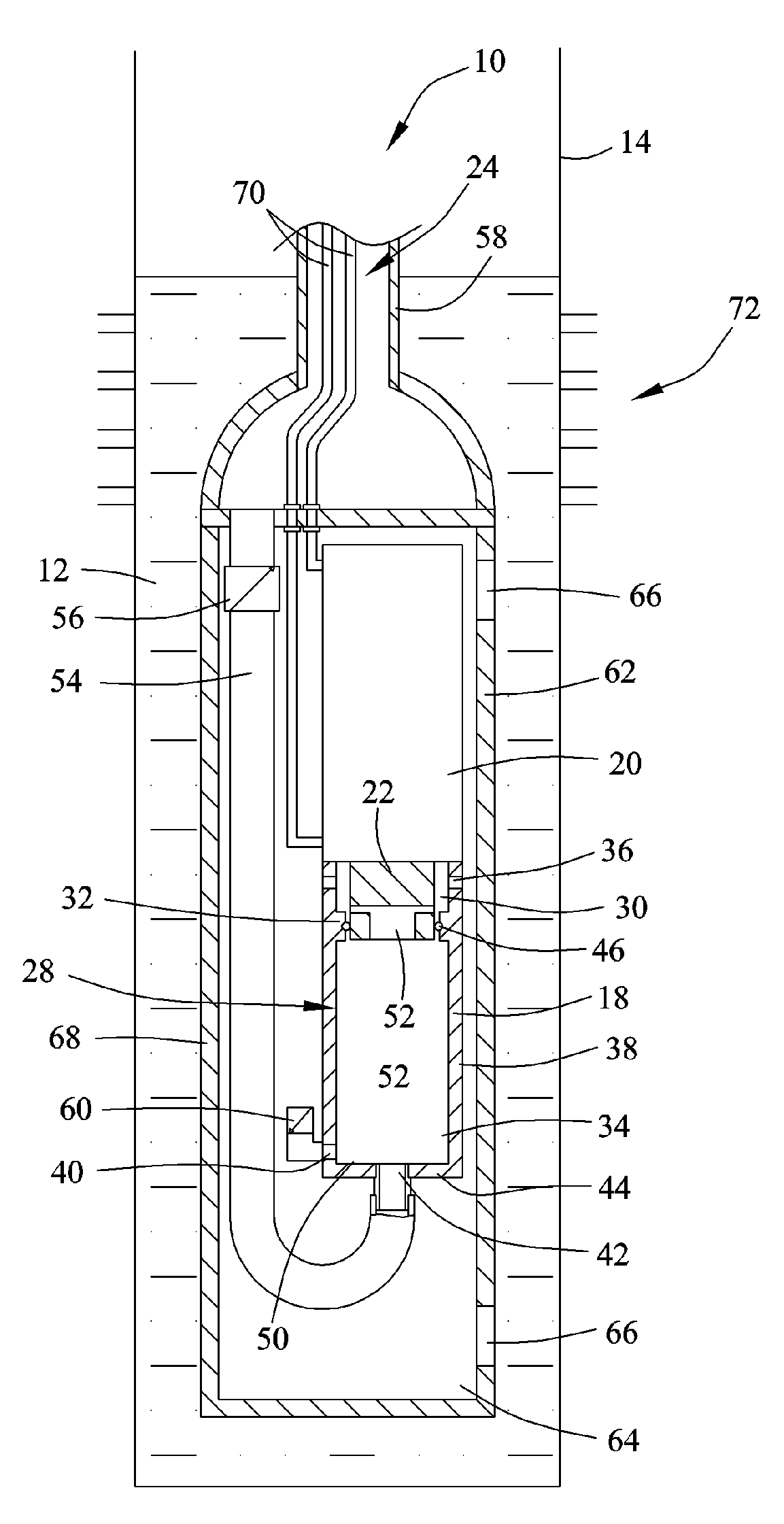
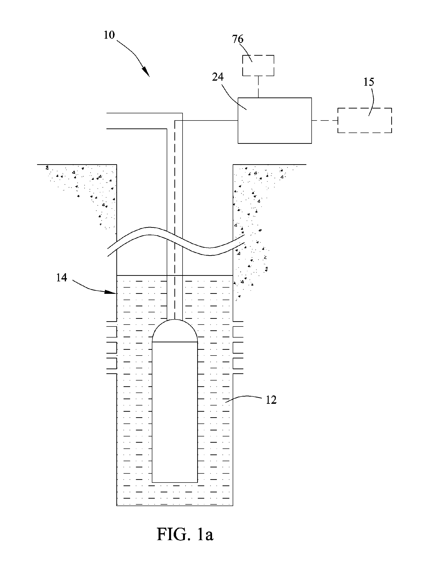
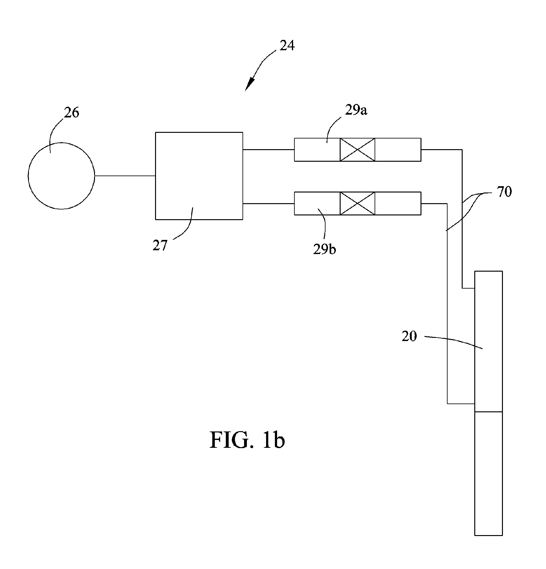
[0025] Referring now to the drawings, and particularly to FIGS. 1a-3b, a preferred embodiment of the pump apparatus 10 is illustrated. With reference to FIG. 1a, the pumping apparatus 10 is employed to lift formation fluid 12 from the well 14 to “unload” the well and restore it back to flow production. The formation fluid 12 can be water, oil or any other liquid gas mixture which is present downhole the well 14 to be pumped from one location to another. In addition, while the pump apparatus 10 is shown to be lifting the formation fluid 12 from a conventional gas well 14, the pump apparatus 10 will work as well in any other environment where its particular features would be beneficial.

[0026] The pump apparatus 10 essentially includes a pump body 18, a hydraulic head 20 connected to the pump body, a reciprocating displacement plunger 22 connected to and operated by the hydraulic head 20 to reciprocate within the pump body to draw-in formation fluid 12 and displace it from the pump bo...


PUM


Abstract

A method and pump apparatus for removing formation fluids from a “liquid loaded” gas well is provided. The pump apparatus is adapted to be positioned downhole a well and is hydraulically operated to lift formation fluid, such as water from the well to “unload” the well and reestablish gas production. The pump apparatus includes a pump body, a hydraulic head connected to the pump body, and a displacement plunger operated by the hydraulic head to reciprocate the displacement plunger within pump body to draw-in and displace formation fluid from the pump apparatus. The pump apparatus is a fluid displacement type pump and has a low power consumption affording use of the pump apparatus at even the most remote well locations. Additionally, a method of operating the pump apparatus is provided

Description

CROSS REFERENCE TO RELATED APPLICATIONS [0001] This application is a continuation in part (CIP) of co-pending application Ser. No. 10 / 926,424 filed Aug. 26, 2004, the entirety of which is incorporated herein by reference.FIELD OF THE INVENTION [0002] The present invention relates generally to methods and systems for lifting fluids from a well. More particularly, relating to a method and apparatus for removing formation fluid, such as water from a low production gas well to reduce static pressure within the well created by the formation fluid, thereby increasing production of gas from the well. DISCUSSION OF THE PRIOR ART [0003] Many gas wells experience decreased gas production over the service time of the well, and some eventually cease gas production completely. Factors causing this problem include declining reservoir pressure and gas velocities, and increased liquid production. The increased liquid production can results in a column of liquid to accumulating at the bottom of the ...

Claims


Application Information

Patent Timeline
Patent Type & Authority Applications(United States)
IPC IPC(8): F04B35/04F04B53/12
CPCF04B53/12
Inventor LIKNES, ALVIN
Owner LIKNES ALVIN
Learn More